• Steel Soldiers now has a few new forums, read more about it at: New Munitions Forums!

  • Microsoft MSN, Live, Hotmail, Outlook email users may not be receiving emails. We are working to resolve this issue. Please add support@steelsoldiers.com to your trusted contacts.


Looking for wiring diag for Pos Term, Neg Term, Suppressor

bubbagump

New member
9
3
3
Location
Nashville Tn
Hey yall,

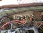
I've been digging around and I haven't been able to find anything that appears to show the connectivity between the wires in the Pos Term, Neg Term, Suppressor.

My junction block is completely shot and I'm trying to figure out a way to fix it or replace it. (haven't had any luck finding a replacement part.)

What I"m really looking for is something like a wiring diagram so I can tell what's connected to what. I mean would it be possible to connect all the Pos term wires together and all the Neg term wires together? I can't tell from what I've found how it actually works.

Thanks in advance.
 

MarcusOReallyus

Well-known member
4,524
810
113
Location
Virginia
Rick? Did you mean to include a link? There's nothing there to check out.

bugabump, the TMs (Technical Manuals) are available for FREE download here on Steel Soldiers. The wiring diagrams are in the -20.

You can also find a ton of good info in the "Helpful Threads" sticky at the top of the forum.


Whatever you do, don't start changing things around until you KNOW what you are doing! The CUCV has a very different electrical system from civilian vehicles. It's a hybrid 24/12 volt system, and most people find it pretty confusing at first. You can make smoke pretty easily.

Post some pics of what you are working on and we can help you get it sorted out.
 

bubbagump

New member
9
3
3
Location
Nashville Tn
Thanks for the info. I have not had time to look at it all in detail yet. I'm planning to on my next day off.

I don't have photos as the truck is at a different location. Truck is 1984 M1009 all stock other then some jury rigging by previous owners.

The two biggest wires going to the same bolt on the block have kind of melted together and not wit won't start. I checked batteries, terminals etc.

The biggest question I have is whether the everything that bolts into the top is electrically connected. (I'm not planning on doing this but for the sake of understanding) If I were to unbolt everything connected to the top and put them together on one big junction block would it work or are there different pathways through that junction block?

When I try to start it all I get is a click. I tried tapping on the starter but I'm not getting anything. I took the truck to a different location of the place that installed the starter as is would still be under warranty but they said they have no way of testing the starter. (which I suspect may be the problem)

What I'd like to do is clean up the whole thing and if there is something that I can replace the block with that would be the best, however I'm haven't been able to find one.
 

coecamo

Member
42
0
6
Location
Canton Mich
Top Terminal block is all common connected 24 Volts. 2 Largr wires Are Positive Right Battery, Battery Supply to starter. melted look is usualy bad this will need to be repaired and clean. If you have a slave connector at the grill there will be a 3rd heavy cable as well. IMO stacking all high current and other 24 V wires on 1 bolt will be difficult to keep good tight connections. try Hilbuly Wizard I bought parts from himin the past. good luck Gary
 

bubbagump

New member
9
3
3
Location
Nashville Tn
Hey all,

Oh boy. Against my better judgement I took it in to a shop that assured me they knew how to work on these. They replaced the started and fixed up my wiring for too much money.

The truck starts but now I have a new set of problems and I'm doubtful they will be able to fix it.

When I turn the key to start I do not hear that characteristic sound that the glow plugs make when they turn on or when they turn off. In addition to this the glow plug seem to stay on for about double the amount of time they did before.

When it finally goes off it drags when it goes to start as if the batteries are almost dead.

When I'm driving my amp meter needle is also buried to the left, as if it's not reading anything.

Any ideas?

Thanks in advance.
 

cucvrus

Well-known member
11,274
9,601
113
Location
Jonestown Pennsylvania
The voltmeter is could be as easy as a blown 10 amp fuse at the bottom of the fuse box. Replace that and look at how the charging system is working. Have the batteries load tested. They may be weak. And is this still 24 volt? Report back your findings and Good Luck.
 

bubbagump

New member
9
3
3
Location
Nashville Tn
Aye. It was working until they "fixed the wiring" so I didn't think to check the fuse.
The batteries are rather new so I didn't think to have them tested.
Yes, it's still 24 volt.

I'll take photo tomorrow as I don't get off work until late tonight.
 
Last edited:

bubbagump

New member
9
3
3
Location
Nashville Tn
I'm not currently at the truck to check but I will when I get home.

From what I recall before only the gen1 light would come up when the truck was in the glowplug/on position. What should it be?
 

cucvrus

Well-known member
11,274
9,601
113
Location
Jonestown Pennsylvania
Both must light for the charging system to operate as designed. If you are only charging the front battery that would explain the slow / long glow plug cycle and the slow cranking. You are basically starting and operating on a low rear battery and Gen 2 is not charging as designed. Does it seem to charge after you get the RPM's up. Check that fuse and report back. But if it is not charging on both generators that will make everything work as you described it. Also that low voltage / amperage is very hard on everything and especially the new starter. Check all your fuses closely. Also the fusible links at the 12 volt power point. Good Luck.
 

v12venator

Member
59
30
18
Location
Raeford, NC
Hey bubbagump, just figured I would show you what I've done to make my 1031 work with an under the hood electrical kill switch. In case you wanted to make any adjustments, since a picture is better than a wiring diagram for some things.

IMG_20200427_134147.jpg

The longer negative cable goes to the middle connection on the lower 3 post bar from the negative post on the front battery. The main positive cable routes from the second lug on the top 5 post bar to the positive terminal on the rear battery. Then between the positive on the front battery and the negative on the rear battery is a joiner cable that gives you the 24 volts. Hope this helps.

V12venator
 

bubbagump

New member
9
3
3
Location
Nashville Tn
Thanks. I should have photos shortly.

I found another thing they broke. My hood release would work but you would have to bang on the hood to release it. Now it's not working properly. If you bang on it it won't open. It has to be forced open. Any pointers on how to fix that?

Thanks for all the help. I really do appreciate it.
 

Attachments

v12venator

Member
59
30
18
Location
Raeford, NC
Thanks. I should have photos shortly.

I found another thing they broke. My hood release would work but you would have to bang on the hood to release it. Now it's not working properly. If you bang on it it won't open. It has to be forced open. Any pointers on how to fix that?

Thanks for all the help. I really do appreciate it.
So, for the hood latch system on your truck, it should be a two piece kit. The first will look like this
IMG_20200427_192837.jpg
Any binding with this or a deformed spring on the back
IMG_20200427_192848.jpg
can cause issues when releasing the hood. For this, I would try soaking the pin on the back where your claw articulates at with PB Blaster. Once you are sure that is free and moving, I would check and see if your spring is moving as it should by manually rotating the claw back and forth.

Also to note here is that the release cable that leads into your cab may have some crud in there as well, and a run through of PB Blaster can help with this.

Should you find that the issue is not with your first stage of hood release, you will want to next take a look at the hood mounted release arm in the center of the front of the hood like this one.

IMG_20200427_192853.jpg
IMG_20200427_192859.jpg

Same thing applies here with the PB Blaster and making sure there is no 35 year old crud freezing your arm and spring. Thankfully, both of these parts are GM factory, so you should be able to get them at your local parts store without any issues if you find that one of them is broke beyond repair.

As for your wiring from the picture, you should remove the black lead cable from the number 5 post on the top bar and move it to the number 2 post on the bottom bar.

EDIT: I have attached a picture of mine for reference.
IMG_20200427_195037.jpg
 

Miah

Member
90
29
18
Location
Kansas City-ish, MO
As for your wiring from the picture, you should remove the black lead cable from the number 5 post on the top bar and move it to the number 2 post on the bottom bar.
Are you SURE about that? From the pic i suspect that wire on #5 post is the primary cable from the back battery & if so i really don't believe it should be hooked to the ground bar.

BG: It's not much of an overall pic, but if you paid a shop too much money for that cabling as part of the repairs, then there is def a bubbagump involved, but it's NOT the owner of the truck.
 

bubbagump

New member
9
3
3
Location
Nashville Tn
I sure am learning many things from this. First off I should have taken a photo BEFORE I took it to the shop.

If you see the second bolt where it is damaged, I think there were two wires there. I think they moved them to another bolt. It looks like the two wires that were on the second bolt were moved to the last bolt as I seem to recall them being rather large wires. Would that make any sense?
 

Miah

Member
90
29
18
Location
Kansas City-ish, MO
Your 3 big wires on the top 24V should be that black one i suspect is the battery cable, the other 2 should be 1 running forward to the slave port in the grill & then 1 running underneath & back to the radio bus inside the cabin by the back seat.

Any other pics of the batteries, terminals certainly won't hurt for us to help you diagnose issues.
 
Top
AdBlock Detected

We get it, advertisements are annoying!

Sure, ad-blocking software does a great job at blocking ads, but it also blocks useful features of our website like our supporting vendors. Their ads help keep Steel Soldiers going. Please consider disabling your ad blockers for the site. Thanks!

I've Disabled AdBlock
No Thanks