• Steel Soldiers now has a few new forums, read more about it at: New Munitions Forums!

  • Microsoft MSN, Live, Hotmail, Outlook email users may not be receiving emails. We are working to resolve this issue. Please add support@steelsoldiers.com to your trusted contacts.


Advice needed - new guy with MEP004A

Back-in-Black

Well-known member
295
275
63
Location
Louisiana
Someplace there is a wire that sends DC voltage to the main gen to light it off. Follow the F1 and F2 wires backwards.
Now that makes a heck of a lot more sense than what I've been getting looking at that schematic and reading "principle" articles. It's like the initial excitation voltage is pulled straight out of the air going by all that.

I'll go trace those wires.
 

Back-in-Black

Well-known member
295
275
63
Location
Louisiana
Damn, just found out I know a lot less about how this thing was modified than I thought I did - and I didn't think I knew all that much about it but I thought I at least had the basics figured out.

The field wires on that AVC go to the Delco alternator. One appears to be the ground and the other the field exciter going into the alternator (thru a 12 Ohm resistor). So apparently, this AVC is the regulator for the belt operated alternator mounted to the front of the motor.

I got some serious wire tracing ahead of me now.


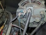
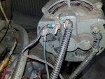
In the pic below, the F+ from the AVC goes to a 12 ohm resistor and then to the connector going into the back of the alternator (marked F for field I assume). The other wire (F-) goes to the black wire with the blue crimp on lug attached to what looks like the alternator ground (long stud sticking out of rear of alt).

But all this still doesn't make sense as even for that alternator, there's still no source of voltage for the initial field excite. And yes, I started the motor again and checked - no voltage out of the alternator. Like I said, I got some wires to trace and try to figure what in the heck these guys had rigged up here.


12 ohm resistor
20211113_173532.jpg

20211113_173538.jpg
 

Scoobyshep

Well-known member
914
989
93
Location
Florida
Follow F1 and F2 from the main generator head. It should go to some form of regulator and there should be something going back to battery (through some form of switch) as modified as your set is its gonna be alot of reverse engineering.

Sent from my SM-G973U using Tapatalk
 

Back-in-Black

Well-known member
295
275
63
Location
Louisiana
Ah, I thought guyfang was talking about F+ and F- which are on the AVC. - which would have been the same thing if that AVC were actually controlling the main alternator, I'll try to find those two wires in the morning.
 

Back-in-Black

Well-known member
295
275
63
Location
Louisiana
OK, here we go!!!

There is no TB 17, or any of that stuff. Apparently it was all ripped out back when.

And here is the real bizarre one: The Delco alternator does not charge the batteries - at all! It is connected directly to the main alternator's field wires! See picture below:

20211113_173538.jpg

The blue wire on the left, connected to the B+ terminal of the alternator, is directly connected to one of the field wires for the main alt. thru another ceramic, 6.5 ohm resistor. I assume the resistors are for current limiting.

The blue wire on the right (GRD) hooked to the ground lug of the Delco alt. is connected directly to the other main alt. field wire.

There is nothing else. No relays, no battery connection, nothing.

The Delco alt does not charge the batteries, not hooked up to them in any way (there was a 2 bank, marine type battery charger / maintainer on the batteries. And if you think about it, if you plug that charger into "shore power" it will be charging the batteries whether or not the generator is running. And from what I've seen, there will be almost no draw down on 2 good batteries when starting the engine - the thing starts up almost instantly.

So here's what I get from all of this: The AVC is regulating the output of the Delco alt. by doing what it is designed to do controlling the field of the Delco. BUT, it's feedback is not from the Delco's output. I traced those wires a while back and terminals 3 & 4 of the AVC are connected to L1 and L0 of the main alt. Soooooooo, apparently the AVC is indirectly controlling the output of the main alt. by controlling the field of the Delco.

Guessing it works like this: The AVC is monitoring the output of the main alt. When it sees a drop in voltage, it increases the Delco's field supply, thereby increasing the Delco's output, thereby increasing the field supply to the main alt, thereby increasing the main alt.'s output.

Over voltage would work the same way by decreasing the Delco's field supply.

Just thinking about it, I don't see any real disadvantage of doing it this way and it apparently gets rid of a whole lot of voltage regulator components and such because there is none of that stuff left. There are the 2 current limiting resistors on the supply sides of both alt's fields and there is a 2 lug terminal block that is the connection between the Delco's output and the main alt's field wires. And that's it, other than the terminals where the load is to be connected.

2 very small solid state boxes replaced all that stuff. One that controls things like auto start / shutdown on power failure / power restoration, shut down for oil press, over heat and such and the other box is the AVC. Seems mike this really limits potential points of failure. No relays, no voltage regulator with a bunch of capacitors to go soft over time. Just those 2 solid state boxes and an alternator. Not sure this is better but it sure makes it a lot simpler in some ways to troubleshoot if you know how it's wired. (which I'm starting to understand now)

I assume that this Delco is of the self exciting type since there is no battery connection at all. I originally assumed that it was a 24 volt unit but now I don't really know. I'll have to start her back up and see if I'm getting any voltage out of it. It's got a tag on the top but it's been painted over. Guess I need to see if I can clean that off and read the tag.

Still trying to mentally digest all of this...

If the main alt. field is normally excited by feeding back some of the voltage created by the main alt, what range of voltage would be needed at the field to create 240 volts? Apparently, this Delco was / is capable of supplying that... Judging by the AVC (which is actually made to control supply the field on a full size generator), the voltage required by the main field is fairly small? The specs for the AVC list max continuous output power at 4 amps DC @ 63 V DC o/ 252 Watts so if that means what I think it does, the field doesn't take a whole lot of juice to run.

Is the field of the main normally fed alternating current? I gotta assume that the Delco is feeding it AC and it's wired directly for the field with no AC to DC conversion that I can see.

I think right now I just need to figure out if the AVC is smoked or the Delco is not putting out. Sound right?

Just looked up the AVC. I can get a new one for about $50.
 
Last edited:

Back-in-Black

Well-known member
295
275
63
Location
Louisiana
I just started it up and put my meter on the Delco. No AC from it but walking back and checking for DC now.

Just remembered / realized, these old Delcos usually have an internal rectifier / bridge component and put out DC.
 

Back-in-Black

Well-known member
295
275
63
Location
Louisiana
I get 0.13 VDC on the back of the alternator with the motor running. Went ahead and ordered a new AVC since it was so cheap and that fuse was blown like it was. The Delco could still be bad but that should be pretty easy to fix or replace if so.

In the mean time I'm going to do some reading on self exciting alternators...
 

Back-in-Black

Well-known member
295
275
63
Location
Louisiana
Well, tried to manually excite the Delco (as described in the video below). No joy but the output did go from 0.13 to 0.22 VDC. So maybe the AVC is smoked and not charging the field. No clue but the new AVC should be here Wed. and I'll try again then.

 
Last edited:

Back-in-Black

Well-known member
295
275
63
Location
Louisiana
I'm thinking about adding a relay that throws 24 volts from the battery to the hot post of the Delco, and thereby to the main alt field for a few seconds after motor gets to RPM. Not sure I need this yet but seems like a solution that would get everything going dependably. The motor controller that I plan to put on this thing has 2 extra output channels ( one dedicated for fuel pump activation, one for starter solenoid, one for generator breaker close and one for mains breaker close (transfer switch) and 2 programable "spares") . I could program one of the spares to close a relay for a few seconds that would apply 24 volts to the Delco output which would power the field for the main alt. and once that starts producing power, the AVC will use that voltage to power the field on the Delco.

Like I said, not sure I even need this but pretty sure it would work if I do. I could even change it around a little and use a non-self-exciting alternator by just leaving the relay on during run time and hook it to the "ign" lug of a normal alternator.

Typically, how long does the speed switch apply battery voltage to the field in an "unmolested" MEP-004? In other words, how long does it take the main alt. to "light off" and start producing power once that 24 volts is applied to it's field? I'm guessing only a second or 3 but I've already admitted I don't know jack about generators...
 

Scoobyshep

Well-known member
914
989
93
Location
Florida
I believe that the speed switch only enables the field flash. Once a set rpm is reached the starter is disabled and the flash is enabled, the start switch needs to be held in the start position to flash. So the answer would be as long as the operator is holding the switch. I have seen them take upwards of 5 seconds to come up to voltage and as low as half a second. Most people ignore the flash time as they are watching for oil pressure to come up.

Sent from my SM-G973U using Tapatalk
 

Back-in-Black

Well-known member
295
275
63
Location
Louisiana
So the speed switch disconnects the starter solenoid and closes the "flash" relay? Makes sense.

So don't watch RPM, watch oil pressure? That's easy enough. I guess I could program the flash to last until the main is putting out some preset amount of voltage. I briefly read thru the programming guide for this controller but don't remember how it handles "if-thens". I would think that attaching conditions to a "programable output" is the definition of "programable output" so watching oil press before closing the "flash" relay should be pretty simple. It has dedicated inputs for oil press, coolant temp, fuel level and shore power monitoring.

Still not sure I need to do this but seems like an easy solution to "lighting it off".

Thanks for the input!
 

Scoobyshep

Well-known member
914
989
93
Location
Florida
So the speed switch disconnects the starter solenoid and closes the "flash" relay? Makes sense.

So don't watch RPM, watch oil pressure? That's easy enough. I guess I could program the flash to last until the main is putting out some preset amount of voltage. I briefly read thru the programming guide for this controller but don't remember how it handles "if-thens". I would think that attaching conditions to a "programable output" is the definition of "programable output" so watching oil press before closing the "flash" relay should be pretty simple. It has dedicated inputs for oil press, coolant temp, fuel level and shore power monitoring.

Still not sure I need to do this but seems like an easy solution to "lighting it off".

Thanks for the input!
The factory units teed the start switch held because it bypasses the low oil pressure shutdown. Since your unit is far from factory you can monitor what you would like. You really need to monitor oil pressure while running, on startup you should disengage the starter above the crank rpm, If you are slow to build oil pressure and the engine has fired but the starter is still engaged due to low pressure the starter will not have a good time. so in start sequence monitor rpm. as for oil pressure monitor it and there really needs to be a means of shutdown for loss of/ failed to make oil pressure.
 

Back-in-Black

Well-known member
295
275
63
Location
Louisiana
Talked to the guy who gave it to me yesterday - forgot to strangle him for being nice enough to give me this project- LOL. He had looked at it back when. He never realized that the Delco was feeding the field of the main and that the AVC was actually controlling the field of the Delco but he had also come to the same conclusion - the AVC is smoked.

My plan is to basically do this like a pro-built genset: Auto shutdown on low oil press, and over temp. I think auto shutdown on over-voltage for too long is a native feature of the controller. Pretty sure I read that in there at one point. Auto shutdown on low fuel is probably also possible but I can imagine scenarios where that could become a problem. Probably best to just let it run out of fuel.

A tach would be really nice. I have the MPU and I'm assuming it works but I would love to know how many teeth the flywheel has so I can set that up. I guess I'm gonna have to work into that backwards from 60 Hz operation and knowing that that is 1860 RPM. I dug around on the internet for an hour or so looking for that little tidbit (how many teeth) and could not find it. I guess I could also put an oscilloscope on the MPU output and turn the motor over 1 revolution by hand and count the square waves. That would be easier than separating the motor and main alt to count flywheel teeth. We'll see how accurate I can get it working from 60 Hz.

The controller I plan to buy also has an input for an "emergency stop" so I will probably put one of those big, red stop operators / buttons on the control panel.

New AVC should be here tomorrow - hopefully I can make some power with that and then I can really dump some money I don't have into this thing LOL.

I took pictures and measurements of the metal plate and gauge holes and such for the control panel. I may start drawing up a new plate tonight in AutoCAD and send that to a local guy that cuts out stuff like that with a water cutter. Might end up sending it to a panel builder for cut out. The local guy (that I know) does heavy industrial stuff and his machines are running full speed. He may want to charge me a fortune to do a one-off, small job like that. We'll see. Also thinking silk screen for labels but no clue what's involved there. Maybe getting the labels engraved with a CNC router and doing the paint and wipe thing would be a better choice.

Watching the RPM for starter disengage makes sense. When I really start that part of all this I'm sure I will be driving you nuts with dumb questions!
 
Last edited:

Ray70

Well-known member
2,354
5,009
113
Location
West greenwich/RI
Sounds like you have already decided what you want to do for control system, but if things change, I wonder if this gen would be a good candidate for an SX-460 AVR?
I've used them a few times on different military gens and they have worked well every time.
 

Back-in-Black

Well-known member
295
275
63
Location
Louisiana
Sounds like you have already decided what you want to do for control system, but if things change, I wonder if this gen would be a good candidate for an SX-460 AVR?
I've used them a few times on different military gens and they have worked well every time.

I've only "picked one out" in the sense that I haven't seen anything better yet but I will definitely look at this one. Hadn't seen it before and if you recommend it, then it's definitely on the list.
 

Scoobyshep

Well-known member
914
989
93
Location
Florida
Sounds like you have already decided what you want to do for control system, but if things change, I wonder if this gen would be a good candidate for an SX-460 AVR?
I've used them a few times on different military gens and they have worked well every time.
Will that work? spec sheet calls for a minimum of 15 ohms. 004 field winding is 2-4 ohms.
 

Guyfang

Moderator
Staff member
Moderator
15,816
21,957
113
Location
Burgkunstadt, Germany
Wellllllllllllllllllllllllllllllllllll,

In a normal 004A, the S9-1 contacts are closed, (pins A&B) on start up. Those pins allow the starter solenoid to do its thing and the starter turns the engine. At a certain RPM, (look in the TM if you want to know) the S9-1 contacts reverse. Pins A&B open and drop the Starter solenoid out, and pins A&C close, and 24 volts goes to the main gen, excitation roter, to light off the main gen. At that point, you let go of of the start switch, and K6, (if I remember right) reverses contacts and allows the Volt Reg/static exciter to control the production of AC from the main gen. But the speed switch is not what controls the K6.

Spur Gear:

TEETH QUANTITY135


So the speed switch disconnects the starter solenoid and closes the "flash" relay? Makes sense.

So don't watch RPM, watch oil pressure? That's easy enough. I guess I could program the flash to last until the main is putting out some preset amount of voltage. I briefly read thru the programming guide for this controller but don't remember how it handles "if-thens". I would think that attaching conditions to a "programable output" is the definition of "programable output" so watching oil press before closing the "flash" relay should be pretty simple. It has dedicated inputs for oil press, coolant temp, fuel level and shore power monitoring.

Still not sure I need to do this but seems like an easy solution to "lighting it off".

Thanks for the input!
 
Top
AdBlock Detected

We get it, advertisements are annoying!

Sure, ad-blocking software does a great job at blocking ads, but it also blocks useful features of our website like our supporting vendors. Their ads help keep Steel Soldiers going. Please consider disabling your ad blockers for the site. Thanks!

I've Disabled AdBlock
No Thanks