• Steel Soldiers now has a few new forums, read more about it at: New Munitions Forums!

  • Microsoft MSN, Live, Hotmail, Outlook email users may not be receiving emails. We are working to resolve this issue. Please add support@steelsoldiers.com to your trusted contacts.


Automatic / Manual Fieldflash with aftermarket AVR on MEP004A / 005A

peapvp

Well-known member
Steel Soldiers Supporter
1,032
1,054
113
Location
Basehor, KS
On the A11, the fieldflash is initiated by pushing S1 in Start position.
When engine RPM reaches ~300 rpm the S9-1 switches from NC to NO applying 24V to K5 which then sends 24V through R35 to J9-C which is internally jumpered to J13-S which is your F1 for as long as S1 is in Start position.
once released then excitation stops and VR of A11 takes over.

if you you use an ADVR-054 then you can simply make a jumper from J9-C to F1 (F+) or you can use a Diode (5 A min) with Anode on J9-C and Cathode on F1 (F+)

then you get field flash just as before while starting

Peter

E83EFDFF-C7E1-4AB9-9083-820275D05A50.jpeg
 

peapvp

Well-known member
Steel Soldiers Supporter
1,032
1,054
113
Location
Basehor, KS
On the AVDR 054 the connection between A + C is the AC Voltage Sense Input and can be between 170 VAC to 520 VAC

the connection between B + C is the AC power supply and should be between 170VAC and 300VAC max

i left the B connection open in my wiring diagrams on purpose.

please check the AVDR 054 manual for connecting A, B and C to match your Genset setup for Voltage and Phases
The system as drawn will not provide VR functionality after excitation until B is connected as per AVDR Manual
Thank You
 

peapvp

Well-known member
Steel Soldiers Supporter
1,032
1,054
113
Location
Basehor, KS
Folks,
To clarify this for once and for all:

only the ADVR 053 can be connected to Chassis Ground for field flash.

Oshkosh had sold this ADVR 053 and this is where the idea came from to utilize a Pushbutton, diode and resistor to field flash.

my understanding is that ADVR 053 was discontinued and somehow people started to believe that the ADVR 054 is the sucessor of the ADVR 053, which is incorrect. These are two very different AVR’s

ADVR 053 Manual

8B721CE3-CBBB-4777-9353-BB9D1FDB849E.jpeg
E77CBFA0-52DA-4738-9726-463A07504255.jpeg
DEED818B-9A87-4851-B6A0-81E87D70F65B.jpeg
 
Last edited:

peapvp

Well-known member
Steel Soldiers Supporter
1,032
1,054
113
Location
Basehor, KS
Ok Folks,

After consulting with Kutai Electronics in Taiwan, which is a reseller of this AVR, now the clarification:


The minimum resistance as Load on Terminals F+ and F- is 15 Ohm

Any Coil below 15 Ohm needs to have a series power resistor, which has to be a heavy hitter in terms of power dissipation, as this unit will provide up to 5 Amps continues current up to 63V ( 315 VA ), with peaks up to 7 Amps and 90 V ( 630 VA )

My recommendation would be a 500W 12 Ohm resistor. Your exciter winding should be within specified limits by TM between 2 to 4 Ohms.

This unit, when used with either automatic flash or manual flash should have a paralleled series resistance as constant load of 100 Ohm 100 Watt connected at all times which could be split into two in series resistors with 50 Ohm / 50 Watt each for cost reasons.
Otherwise, the unit may malfunction when no load is attached to F+ and F- and the unit sees a Build Up Voltage on A and C Terminals.

Now as to the automatic self excitation:

This AVR needs to see at least 5 VAC on A and C Terminal to start the exciation process.

This is concurrent with a minimum frequency of 25 Hz which equates to an engine RPM of 750 and over

Their suggestion is, when the unit does not start exciation, to use a Oscilloscope and verify your Frequency on A and C. Make Sure you use a Current / Voltage monitoring probe, otherwise if you connect your Osci Ground Clamp directly to either A, B or C then you will have sparks flying and may suffer damage to your Osci.

All resistors in the attached wiring diagrams will get hot! Provide suitable ventilation and make sure they do not conduct to chassis GND!


Peter
 

Attachments

peapvp

Well-known member
Steel Soldiers Supporter
1,032
1,054
113
Location
Basehor, KS
Folks,
I normally would not recommend these type of epoxied AVR’s for a variety of reasons and concerns, as this is a double-edged sword.

The electronics off all these MEP’s are coming of age. There is no way around this.

Mostly affected are all power related items like the AVR’s and all LCD units.

We can design and built replacement AVR’s here in our facility in the US with the least amount of foreign components as we do with all our other products, but the flip side of the coin is the cost. Especially power electronics and LCD system can get very expensive very quickly because of the very limited choice of US made parts and components, which would meet or better match the quality of the MEP’s on a mechanical level.

I will keep you guys posted on what we can come up with, something which is not going to break the bank, but is equally good as the Gensets themselves.

Peter
 

catienla

Member
32
20
8
Location
anawalt,wv
Peter, if there is a possibility that the 054 is damaged, I will not replace it with another one. I am only trying to have this for emergency use until I can get the VR shipped and rebuilt. Is there any way to check the unit without having to buy anything else? Am I beating a dead horse? I don't have easy access to parts without ordering them and waiting a week. Just wondering. Will try to get VR shipped Tuesday for rebuild. Thanks, Mike
 

peapvp

Well-known member
Steel Soldiers Supporter
1,032
1,054
113
Location
Basehor, KS
Peter, if there is a possibility that the 054 is damaged, I will not replace it with another one. I am only trying to have this for emergency use until I can get the VR shipped and rebuilt. Is there any way to check the unit without having to buy anything else? Am I beating a dead horse? I don't have easy access to parts without ordering them and waiting a week. Just wondering. Will try to get VR shipped Tuesday for rebuild. Thanks, Mike
Mike, this is somewhat difficult to judge from a distance. To test the AVDR 054 you would need at least a 100 Ohm / 100W+ Resistor connected to F+ and F- and then use a variable Transformer 0 to 120VAC connected to C with one leg and the other leg to A+BB (with jumper).
Apply power to unit starting at 0V continunley increasing it and measure VDC across resistor.

DC Voltage across resistor should start at 5 VAC on the AC input on AVDR 054 and then go up to app 63VDC across Resistor as you increase AC

ADVR 054 TEST.jpg
 
Last edited:

peapvp

Well-known member
Steel Soldiers Supporter
1,032
1,054
113
Location
Basehor, KS
While Mike [ @catienla ] was waiting for his A11 to be repaired, we experimented with the ADVR 054 he had bought.

{Edit} Just to make sure: Remove A11 before doing anything else by completely disconnecting J9 and J13!
Also disconnect the two wires from J9 to TB 16! This way the new system is completely separated from the old system!


Here are the results:

After a cumbersome deciphering of several ADVR 054 manuals, which I found on various, US, Taiwanese and Chinese Websites and which all had been translated fairly poorly from Chinese into English, the following facts became clear:

1. The High Voltage supply side [ A, BB, C ] uses A as internal Ground to F-

2. The Minimum Resistance this ( as well as many other ) ADVR needs to connect to for a Exciter Coil Resistance is: 15 Ohm

3. The Maximum Resistance for exciter Coil is: 100 Ohm

4. The minimal residual Voltage for self excitation this ADVR needs on A and C in our wiring connection is: 5 VAC with 25 Hz Minimum

5. Some ADVR 054 ( and other type ADVR ) Manuals suggest the following if the minimum for # 4 is not met:

Disconnect your exciter coil from ADVR and connect to a 7 VDC to 12 VDC Battery {edit} for app 3 to 5 seconds to built up residual magnetism.
They tell you do this while Genset is not running.
Then connect exciter Coil back to F+ and F- on ADVR
( observe correct polarization, F1 lead {edit} should have been connected to + Terminal of 7 VDC to 12 VDC Battery )
Start Generator, observe Voltage and Frequency Gauge on Genset Panel.
Follow the adjustment procedures in the ADVR manual for Stability and Voltage
This assumes the following:
You have installed the correct Rheostat for manual voltage adjustment or
left the jumper on the VR VR terminals

You have connected A BB C correctly to your Generator according to your Voltage Setup!

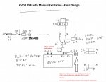
We recommend therefor the following Wire Diagram for a Manual Excitation System (Genset set to 208/230 3P):

AVDR - 054 Wiring Diagram.jpg

The 12 Ohm / 500 W resistor will prevent overload to ADVR for coil resistances below 15 Ohm

The 2pcs 50 Ohm / 50 Watt in series or 1pcs 100 Ohm / 100 W Resistor serves as minimum load and provides with the push button and the Relay the ability to field excite the Genset after the Genset has started.

The ADVR 054 and the SX460 will drive the F+ / F- terminals up to the full AC Input Voltage without a Load Resistor
( hence minimum resistance required )! In our case here, the Maximum Resistance becomes the Minimum Resistance when F1 and F2 are disconnected by the Relay for excitation from ADVR!

This will assure a successful excitation upon every start, even if the Genset sat for a prolonged period of time and has lost any residual magnetism as a result of it.

The ADVR 054 has a 5 Amp Fuse built in for protection.

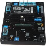
If you use a ADVR like the SX 460 then you want to add two fuses:

1pcs 5Amp Fuse for one leg of the High Voltage Supply and 1pcs Fuse 10 Amp on the F+ leg before the 12 Ohm / 500 W resistor.

I have edited all previous Wiring Diagrams to redirect to this Post #11 in this Thread

If anyone is interested to adapt this system here, to work with the S9 switch for automatic excitation, then please contact me via PM, as this requires further testing and validation.

Mike has currently implemented the above Wiring Diagram and had his House in WV running on this setup for several hours until he ran out of fuel in his Genset. Mike has not done any other testing then this one test as he and his wife are out sick at the moment.

Get well soon!

Peter
 
Last edited:

Mullaney

Well-known member
Steel Soldiers Supporter
Supporting Vendor
7,349
19,037
113
Location
Charlotte NC
It is saying this site cannot be reached. Any ideas? Very curious. Thank you
.
Try this link
 

peapvp

Well-known member
Steel Soldiers Supporter
1,032
1,054
113
Location
Basehor, KS
One word of caution:
@catienla has put this system in his 005A last year (September 2022) and he had it run once for several hours.

He never posted any pictures or videos of the installation.

I have not received any updates on this system as to reliability and performance or problems over time.

I do not have a 004A or 005A here to test, demonstrate or verify this exciter AVR system.

Proceed with caution, and please update us if you implement this system and what your experience is.
Pictures and or video would be good.
I do not make or sell this system.


@catienla had gotten his own parts and had already 2pcs ADVR 054 on his shelf as his A11 had failed some time earlier.

Peter
 

SLTRAM98

New member
18
8
3
Location
North Carolina
Good morning, bumping this thread.
Same issue as noted in the thread, A11 Voltage Regulator (internal board) as pictured has all blown diodes (SEE PIC. M2). Generator at full RPM has 1.7VAC at the main posts in the 120/208 3Phase configuration.

I need clarity on where my SX460 ties into the A11 wiring. I want all the factory gauges and electronics to work, so I am not sure HOW much of the transformers and other components inside the A11 need to be removed. From looking at the wiring diagrams, looks like the SX460 would tie into the Voltage Regulator plug (J11). I have many pictures attached, and the A11 is sitting on my floor so I can get more pictures. Looking for some help on what all is replaced inside the A11 by the SX460 to maintain all the other operating gauges, and items the same (see pic. M5.)

I will posts pictures as I go on this repair, I have searched many places (maybe someone knows of another posts) but there are SO FEW pictures out there.

Thank you all for the help!
 

Attachments

Top
AdBlock Detected

We get it, advertisements are annoying!

Sure, ad-blocking software does a great job at blocking ads, but it also blocks useful features of our website like our supporting vendors. Their ads help keep Steel Soldiers going. Please consider disabling your ad blockers for the site. Thanks!

I've Disabled AdBlock
No Thanks