• Steel Soldiers now has a few new forums, read more about it at: New Munitions Forums!

  • Microsoft MSN, Live, Hotmail, Outlook email users may not be receiving emails. We are working to resolve this issue. Please add support@steelsoldiers.com to your trusted contacts.


Craig tulls drawing (003A)

178
16
18
Location
Jackson NJ
Hello and how are you all. Its been sometime since Ive been on here. Alot has been going on and I have been very busy.
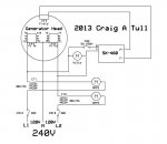
So, this winter I want to get my 003a in the garage to see if I can get it to make power again. What I am interested in doing is setting it up like Craig Tull did. I want to use the machine in 240v single phase . I have no use for 3 phase power. Anywhere.
He eliminated alot of excessive stuff and went with an SX 460 AVR. If Someone can explain his drawing to me I would appreciate it. I am not an electrician and dont quite understand it.
I moved to another location last summer, and now i have more demand for electricity if the power goes out. No power-no water. the 003a would be a big help.
I have a 002a machine thats been getting me through the storms and power outages and its still working. If I can modify the 3a machine to use the sx 460 avr then id also like to do that to my 2a machine.
any help would be appreciated, METALWORKER393
 

Attachments

Scoobyshep

Well-known member
914
989
93
Location
Florida
Should already be setup for single phase 120/240. Is your avr bad? And what part of the drawing do you need explained?

Sent from my SM-G973U using Tapatalk
 
178
16
18
Location
Jackson NJ
Craig's set up , he has the machine running on 240 volt, single phase. He eliminated the selector switch, cvt 1 and 2 , I believe the bridge rectifier , the reactor and I think the main breaker.
What do all the symbols on his drawing mean ?
 

Scoobyshep

Well-known member
914
989
93
Location
Florida
Ah so the your machine is already modified?

Circled M is a meter Volts is directly reading the output voltage
amps is reading the induced field for amperage through CT1 and CT2
CT 1&2 are transformers, they are taking the high current and making it readable to the amp meters

CB 1a/1b main load breaker

CB2 AVR breaker (avr is the voltage regulator the SX-460)
 

Ray70

Well-known member
2,364
5,041
113
Location
West greenwich/RI
Also realize that you have 12 wires plus the 2 field wires coming out of the gen head currently.
You need to accurately connect the appropriate wires together that Craig's drawing shows as internal connections ( T1 through T12 )
Also, I believe CT1 and CT2 are aftermarket transformers, not the original CT/CVT1 assembly to power aftermarket amp gages.
The SX460 is very simple to use. hardest part is just correctly connecting the appropriate wires from the gen head, using an external terminal block, and removing all the unnecessary left over items.
 

Scoobyshep

Well-known member
914
989
93
Location
Florida
Also realize that you have 12 wires plus the 2 field wires coming out of the gen head currently.
You need to accurately connect the appropriate wires together that Craig's drawing shows as internal connections ( T1 through T12 )
Also, I believe CT1 and CT2 are aftermarket transformers, not the original CT/CVT1 assembly to power aftermarket amp gages.
The SX460 is very simple to use. hardest part is just correctly connecting the appropriate wires from the gen head, using an external terminal block, and removing all the unnecessary left over items.

The way he described it, It sounds if he had permanently tapped the windings
 

Chainbreaker

Well-known member
1,747
1,827
113
Location
Oregon

Attachments

Last edited:
178
16
18
Location
Jackson NJ
Should already be setup for single phase 120/240. Is your avr bad? And what part of the drawing do you need explained?

Sent from my SM-G973U using Tapatalk
Hello Scoobyshep, Im trying to eliminate all the garb that goes bad on these machines. I have no use for 3 phase power, and always run my 002a in 240v configuration anyway. I can get an sx460 fairly easy and if it goes bad i can replace it fairly inexpensivly. Im trying to get my 003a repaired and making power again. If this works ill do it to my 002a machine.
 
178
16
18
Location
Jackson NJ
Seems simple enough, I can try to guide you through repairing it
Good day scoobyshep ,how are you. I would appreciate your help with this if you can. This mod was done several years ago by Craig A Tull. His post was titled Civilizing the MEP 002A This is how i would like to wire both my 002a (currently running) and my 003a ( currently not producing any power)
So I spent some time this morning comparing schematics between the 002a and the 003a, and from what i can tell the wires and gauge size is the same between the 2 machines. From Generator end to S6 same numbers and gauge size. so at least i have that going for me.

On Craigs post #13, he has a picture of the leads he is using to a terminal block exposed to the weather. Couple questions here.
I cannot tell , and i dont know what are the lead numbers he has together. I understand on 1 side of the block he has 2 leads together for each position. Which wires are tied together? and, what is this configuration? is this a Double Delta , Low zig zag, or high zig zag? On the closer side of the block in the picture, he has 2 black wires going to where you would connect for a feed ( in my case i want to retain the connection box) Then if you look he has a white "jumper" in the shape of a u , and another white wire im guessing will be the neutral to how he connects to the load.
There is also an older wire coming from the closer side of the terminal block, gong to....? i dont know where.
In this post (#13) Craig tied together leads T8 & T10 and T2 & T4 Ten tucked them into the harness. I believe these are for 3 phase power not being used?

So what i would like to do is tie T8 & T10, then T2 & T4 together inside the connection box so They will be not exposed using Polaris connectors. Craig cut the Cannon connectors off the ends of the leads. I would like to do that inside the connection box, then Im retaining the oem connection externally and a safer connection in my view.
So if this seems plausible the heavy wires on the generator are 1 issue that need explaining.single phase mep 003a 240v.JPG
mep 002a alternator wire conversion.jpg
 
178
16
18
Location
Jackson NJ
Looking at schematic in TM 5-6115-584-12, pg 62 i think Craig used this double delta connection.
T8 & T10 tied together and tucked in his harness. I will need a 2 wire Polaris connector for this.
T2 & T4 tied together and tucked in his harness. I will need another 2 wire Polaris connector.

T11 & T3 , shows L3 on schematic tie together , need a 3 wire Polaris connector. ( this will become T2 later)
T1 & T12, tie together will need a 3 wire Polaris connector. Shows L1 on schematic (this will stay L1)

T6,T7,T5,T9 will be L0 all neutral. will require a 5 wire Polaris connector. This is where Craig used the Jumper between the 2 center lugs. Still dont know what that older wire is doing coming off of the neutral wires in his picture. Perhaps a ground?
The 5 wire Polaris connector will connect the neutrals and I can run a wire to the L0 lug.
With the 3 wire connector I can tie the 2 leads together and have the 3rd wire attaching to the lug up top in the connection box (now will be L1 & L2, L3 will be removed from lug panel)
Does all of this seem correct? If So I need the following-
Polaris connector, wire size 4-14

2ea 2 wire
2ea 3 wire
1ea 5 wire
Thanks, metalworker393
 

Scoobyshep

Well-known member
914
989
93
Location
Florida
It looks like he wired double delta, And the Polaris connector count is correct. If i had to venture a guess the 3 wires are instrumentation and AVR feed. It looks like it will work that way.

Your 003, did it loose the avr or did a winding fail? Another issue you might have is getting the reaction going, might need a field flash circuit.
 

Chainbreaker

Well-known member
1,747
1,827
113
Location
Oregon
Would be cool if someone like @kloppk developed a drop in AVR 120/240 conversion kit for the -002a/-003a to take the guess work out of it and insure its professionally & safely implemented as all his kits are.

Very few people use the 3-phase capability & if they do, the people that were to convert over to the AVR kit would probably sell their working used AC Reconnection Box, or faulty ones for the working parts, on eBay which would help spares availability for those requiring 3-Phase capability.

I would sign up for at least (2), possibly more, depending on pricing & I bet others would make the switch for reliability purposes as well. The AC reconnection box is the Achillies heel on these units as there are several ways they can fail (Transformers, Switch contacts, Rodent damage to wiring, people who don't heed the warning & turn reconnection switch setting while unit is running :rolleyes:...etc.).

It wasn't much of a problem for the Military having spare AC Reconnection boxes in inventory as it's a a quick swap out with adequate spares on hand.
 
Last edited:
178
16
18
Location
Jackson NJ
It looks like he wired double delta, And the Polaris connector count is correct. If i had to venture a guess the 3 wires are instrumentation and AVR feed. It looks like it will work that way.

Your 003, did it loose the avr or did a winding fail? Another issue you might have is getting the reaction going, might need a field flash circuit.
Good day Scoobyshep. I was running the generator on a normal startup and checkout not actually using it. I heard a tick noise and the gauges went flat. Im at the point with this machine that if I cant get it to make power Im going to machine a flywheel adapter, buy a bellhousing spacer, and install a commercial 240v single phase generator end.
Doing this mod is the last chance on this 003a. this isnt going to cost a heck of alot. If it works and I can prove it out , I'll prep a spare control cubicle for my 002a. I would like to get this done before something breaks on the 2a machine as thats the one I use most. Doing this to the 3a, 1 is getting working again, 2, have a larger machine that would probably power my home including the central air. That would be nice in the summer heat.
 
178
16
18
Location
Jackson NJ
One other thing, The double Delta connection that i copied from Craigs post is different from the one in the TM. Different in which leads are connected. see
TM5-6115-584-12 pg 62 I dont know how much of a difference that makes as I am not an electrician and have no idea how to rewind an alternator or motor.
 
178
16
18
Location
Jackson NJ
Would be cool if someone like @kloppk developed a drop in AVR 120/240 conversion kit for the -002a/-003a to take the guess work out of it and insure its professionally & safely implemented as all his kits are.

Very few people use the 3-phase capability & if they do, the people that were to convert over to the AVR kit would probably sell their working used AC Reconnection Box, or faulty ones for the working parts, on eBay which would help spares availability for those requiring 3-Phase capability.

I would sign up for at least (2), possibly more, depending on pricing & I bet others would make the switch for reliability purposes as well. The AC reconnection box is the Achillies heel on these units as there are several ways they can fail (Transformers, Switch contacts, Rodent damage to wiring, people who don't heed the warning & turn reconnection switch setting while unit is running :rolleyes:...etc.).

It wasn't much of a problem for the Military having spare AC Reconnection boxes in inventory as it's a a quick swap out with adequate spares on hand.
Chainbreaker agree with you on that, one of my parts units i Had a mouse got into the reconnection box and destroyed the harness . Plus the switches for voltage selection needs to be cycled periodically to clean the contacts. Too much garb in there to go wrong.
 
178
16
18
Location
Jackson NJ

Scoobyshep

Well-known member
914
989
93
Location
Florida
One other thing, The double Delta connection that i copied from Craigs post is different from the one in the TM. Different in which leads are connected. see
TM5-6115-584-12 pg 62 I dont know how much of a difference that makes as I am not an electrician and have no idea how to rewind an alternator or motor.
winding numbering should be fairly standard, but how you restructure them can slightly change. I would use the diagram form the TM as that is how it will get tapped with the reconnection switch.
 
Top
AdBlock Detected

We get it, advertisements are annoying!

Sure, ad-blocking software does a great job at blocking ads, but it also blocks useful features of our website like our supporting vendors. Their ads help keep Steel Soldiers going. Please consider disabling your ad blockers for the site. Thanks!

I've Disabled AdBlock
No Thanks