


kurtkds
Member
- 629
- -1
- 18
- Location
- Puyallup, WA
There have been many questions about the Fording kit that I have on my Deuce, so I've been working on a list of aftermarket parts and instructions on how to install it.
To start off, this not not a complete instruction on how to install a fording kit on the Deuce, that being said if you have questions that are not covered in this post, feel free to ask and I'll answer the best I can.
Following is a fairly complete list of supplies that I used to make the fording kit, these parts can be purchase from McMastercarr.com so I will use their part numbers as reference.
The List, part number first then quantity and description.
5727K15 8' 1" marine grade hose
5727K183 10' 1 1/4" marine grade hose
36635K42 1 Mushroom vent cap
41735K101 1 Low pressure Air Regulator
5096K32 1 1/4" NPT manifold
5499K202 5' 4" Rubberized flex hose
7767T35 1 6' X 4" O.D steel pipe
3042T19 2 3 1/4" U bolt Clamp
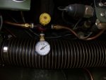
3847K11 1 0-15 PSI pressure gauge
Additional parts would include 1/4" and 5/16" compression fittings, 5/16" copper tube, 1/4" poly tube, assorted hose clamps and assorted pipe Tee's and nipples and a 1/2" ball valve. Also 4' of 1X 3/16" steel flat bar. Air switch.
The supply list will get you started and will allow for cut to fit for most applications.
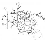
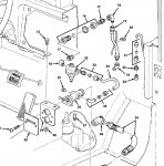
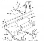
I used the TM 9-2320-361-34P to get an idea of how the fording kit is setup and went from there.
The first two pictures are from the TM showing the official Kit.
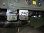
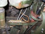
Starting in the cab I used a air switch that is used to activate the front axle to supply air to the pressure regulator. (pic #3) I had the complete assembly so I flipped the plate over for now. In addition I wired the indicator so that when the fording kit was active I would have the light on also. I tied the air supply for that valve into the air switch supply from the valve next to it.
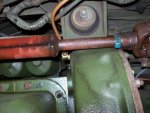
From the air switch the copper line goes to the pressure regulator then continues down through the floor via the transmission cover, there is a space provided between the fire wall and cover for the pipe to go through. The copper line then goes to the manifold that I attached to the frame rail next to the master cylinder (pic #5). There has been discussions on here about what the pressure regulator should be set at, I settled on 2 PSI.
Since have a winch on the truck I ran copper line from the manifold to the port that is located on the bell housing for pressurizing that section of the system (pic #6). You will see in picture #5 the 2 poly tube lines going from the manifold to the vents in the transmission and transfer case for additional protection against water intrusion. To access those vents you will have to pull the covers off from inside the cab, vent for tranny is in front of the shifter tower and vent for transfer case is on top towards the back. The extra ports on the manifold will eventually go to each of the vents on the axles to help keep water out of there.
Going to the engine bay, I ran the 1" hose from the air intake on the compressor to the fitting on the side of the air filter housing. (not pictured yet but visible in pic #1 item 6).
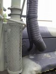
Next was running the hose from the slobber tube up and out of the engine compartment. Since the original kit had a "J" tube for this purpose, it was not hooked up until needed otherwise it could fill with liquid and effectively block off the slobber tube and not allow the crank case to vent. I got around this problem by using brass pipe fittings and a valve (pic #7). On the other end of the hose I installed a small mushroom cap with a pipe nipple to give it a finished look and to help keep insects out (pic #9).
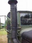
The valve stays open to allow liquid to drain under normal operation but closed when fording. The hose is routed up and out next to the air intake (pic #8 ) you will have to drill a hole through the side panel. I have seen the slobber tube routed directly to the air cleaner instead, but I have concerns about running damp oily air directly into the air cleaner doing damage to the filter.
The intake hose will need two brackets attached to the exhaust stack to support the intake pipe, I used the flat bar to create a clamp to hold the flex hose next to the exhaust stack leaving a gap of approximately 4" to keep the hose from melting the 2 3 1/4" U bolts to attach this assembly to the exhaust pipe (pic #8 ).
Cut a 12" length of steel pipe to be used as the connection between the air intake mushroom that will be relocated and the 4" flex pipe that attached to air filter housing (pic #9).
If you look closely you will see that I originally used 4" electrical conduit clamps to help create the clamp that wraps around the 4" flex tube, they have worked fine, but I'm going to redo them to give it a more finished look. So I have left that off the parts list and added more flat bar instead.
The last item from the original Kit is a check valve (pic #10 item 7) that isolates the primary air tank from the secondary air tank to prevent total loss of air to the system due to a failure in the fording kit air system has not been covered in this post, since I have not gotten there yet.
Keep that in mind as you are working on this project.
To start off, this not not a complete instruction on how to install a fording kit on the Deuce, that being said if you have questions that are not covered in this post, feel free to ask and I'll answer the best I can.
Following is a fairly complete list of supplies that I used to make the fording kit, these parts can be purchase from McMastercarr.com so I will use their part numbers as reference.
The List, part number first then quantity and description.
5727K15 8' 1" marine grade hose
5727K183 10' 1 1/4" marine grade hose
36635K42 1 Mushroom vent cap
41735K101 1 Low pressure Air Regulator
5096K32 1 1/4" NPT manifold
5499K202 5' 4" Rubberized flex hose
7767T35 1 6' X 4" O.D steel pipe
3042T19 2 3 1/4" U bolt Clamp
3847K11 1 0-15 PSI pressure gauge
Additional parts would include 1/4" and 5/16" compression fittings, 5/16" copper tube, 1/4" poly tube, assorted hose clamps and assorted pipe Tee's and nipples and a 1/2" ball valve. Also 4' of 1X 3/16" steel flat bar. Air switch.
The supply list will get you started and will allow for cut to fit for most applications.
I used the TM 9-2320-361-34P to get an idea of how the fording kit is setup and went from there.
The first two pictures are from the TM showing the official Kit.
Starting in the cab I used a air switch that is used to activate the front axle to supply air to the pressure regulator. (pic #3) I had the complete assembly so I flipped the plate over for now. In addition I wired the indicator so that when the fording kit was active I would have the light on also. I tied the air supply for that valve into the air switch supply from the valve next to it.
From the air switch the copper line goes to the pressure regulator then continues down through the floor via the transmission cover, there is a space provided between the fire wall and cover for the pipe to go through. The copper line then goes to the manifold that I attached to the frame rail next to the master cylinder (pic #5). There has been discussions on here about what the pressure regulator should be set at, I settled on 2 PSI.
Since have a winch on the truck I ran copper line from the manifold to the port that is located on the bell housing for pressurizing that section of the system (pic #6). You will see in picture #5 the 2 poly tube lines going from the manifold to the vents in the transmission and transfer case for additional protection against water intrusion. To access those vents you will have to pull the covers off from inside the cab, vent for tranny is in front of the shifter tower and vent for transfer case is on top towards the back. The extra ports on the manifold will eventually go to each of the vents on the axles to help keep water out of there.
Going to the engine bay, I ran the 1" hose from the air intake on the compressor to the fitting on the side of the air filter housing. (not pictured yet but visible in pic #1 item 6).
Next was running the hose from the slobber tube up and out of the engine compartment. Since the original kit had a "J" tube for this purpose, it was not hooked up until needed otherwise it could fill with liquid and effectively block off the slobber tube and not allow the crank case to vent. I got around this problem by using brass pipe fittings and a valve (pic #7). On the other end of the hose I installed a small mushroom cap with a pipe nipple to give it a finished look and to help keep insects out (pic #9).
The valve stays open to allow liquid to drain under normal operation but closed when fording. The hose is routed up and out next to the air intake (pic #8 ) you will have to drill a hole through the side panel. I have seen the slobber tube routed directly to the air cleaner instead, but I have concerns about running damp oily air directly into the air cleaner doing damage to the filter.
The intake hose will need two brackets attached to the exhaust stack to support the intake pipe, I used the flat bar to create a clamp to hold the flex hose next to the exhaust stack leaving a gap of approximately 4" to keep the hose from melting the 2 3 1/4" U bolts to attach this assembly to the exhaust pipe (pic #8 ).
Cut a 12" length of steel pipe to be used as the connection between the air intake mushroom that will be relocated and the 4" flex pipe that attached to air filter housing (pic #9).
If you look closely you will see that I originally used 4" electrical conduit clamps to help create the clamp that wraps around the 4" flex tube, they have worked fine, but I'm going to redo them to give it a more finished look. So I have left that off the parts list and added more flat bar instead.
The last item from the original Kit is a check valve (pic #10 item 7) that isolates the primary air tank from the secondary air tank to prevent total loss of air to the system due to a failure in the fording kit air system has not been covered in this post, since I have not gotten there yet.
Keep that in mind as you are working on this project.
Attachments
-
 60.2 KB Views: 312
 -
 100 KB Views: 322
 -
 37.7 KB Views: 357
 -
 31.4 KB Views: 347
 -
 50.3 KB Views: 356
 -
 47.1 KB Views: 353
 -
 67.8 KB Views: 349
 -
 59.1 KB Views: 350
 -
 54.9 KB Views: 349
 -
 73.6 KB Views: 331
Last edited:
