• Steel Soldiers now has a few new forums, read more about it at: New Munitions Forums!

  • Microsoft MSN, Live, Hotmail, Outlook email users may not be receiving emails. We are working to resolve this issue. Please add support@steelsoldiers.com to your trusted contacts.


HanksDeuce - Installing an Ouverson Locker in your Rockwell Axle

HanksDeuce

Well-known member
1,080
237
63
Location
Prairieville, LA
I have a build thread with all of my modifications in it, but this breakout thread will be for those that don't normally read my build thread. It will help anyone trying to search for the necessary reading material so that they too can install an Ouverson Locker in any of their Rockwell axles (front, middle, or rear).

Materials:
- Ouverson Rockwell 16 Spline Locker [Info here]
- Axle Gasket Kit (at least the center chunk gasket)
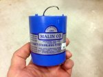
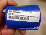
- 0.062" stainless steel (annealed) safety wire [Link here]
- (8) cotter pins for ring gear castle nuts (O'Reilly's or any parts supply house)
- A bunch of Shop Towels!
- Gear Oil
- Neoprene gloves (optional for girly men)
- Pipe

Tools:
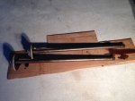
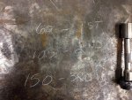
- Hand tools to do the job (breaker bar, wrenches, large screwdriver, hammer, center punch, torque wrenches for as low as 18 ft-lb up to 150 ft-lb)
- 1 ton chainfall
- A few Chokers or chains
- A bucket
- A friend (moral support optional)

Applicable Technical Manual
- TM9-2320-361-34 [Found here]
- Chapter 10

Jargon (may or may not be correct here):
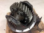
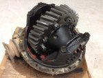
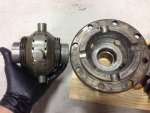
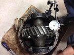
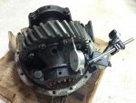
- 3rd member = Center Chunk = Differential Housing = Ginormous thing with the driveshaft going to it.
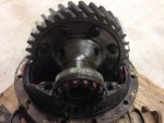
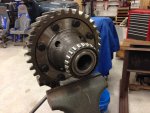
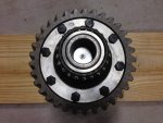
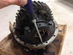
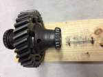
- Bull Gear = Ring Gear = That big round gear with the differential carrier halves bolted to it.
- Bottom gear = Bevel Gear = What connects to the Bull Gear.

Steps:
1) These steps basically work for installing an Ouverson Locker in the front/middle/rear axles on a M35A2. The removal steps below will work better for the middle/rear axles. It is a little more difficult to remove the front differential due to clearance below the engine's oil pan. Some folks have been known to remove the entire front axle assembly for easier access to work on the center chunk.

2) It is not necessary to jack up your deuce, but in the pictures my bobber is on jack stands because I'm changing the bearings and seals due to flood water damage from recent rescue operations in the great 2016 Louisiana Flood.

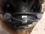
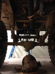
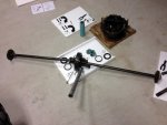
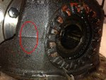
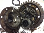
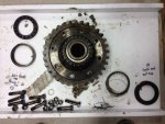
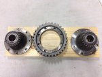
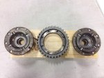
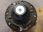
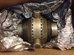
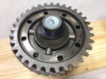
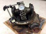
3) Follow the TM starting with Section 10-4. Drain the gear oil. Remove the driveshaft connecting to the differential assembly. Remove the axle shafts from the axle housing.

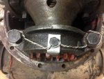
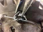
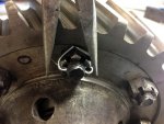
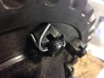
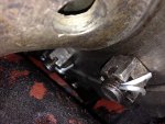
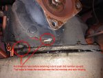
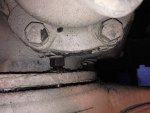
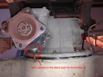
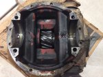
4) Remove the nuts/washers from the open area of the differential. Follow along with the pictures and place a few split lock washers on top of the nuts that are under the pinion gear housing (on both sides). As you loosen the nuts and they travel upward on the studs they will help pick up the differential housing from the axle housing. This technique will help break loose any type of gasket or sealant used between the diff/axle housings.

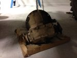
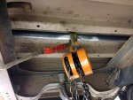
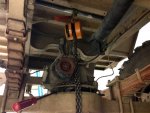
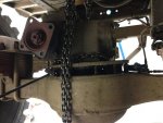
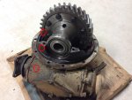
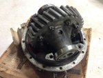
5) Slide your pipe between the bed and the top of the oak that runs under the bed. Wrap a small choker around the pipe and connect it to the lifting hook of the chainfall. If your chainfall has a big enough hook you can connect it directly to the pipe. Wrap a second choker or chain around the differential housing and connect it to the bottom of the chainfall. Remove the differential housing from the axle housing. BE CAREFUL! THIS THING IS HEAVY! Lower the differential housing to the ground/concrete below. Slide it out to an open area for working on it.

Pictures below for Steps 1-5.
 

Attachments

Last edited:

HanksDeuce

Well-known member
1,080
237
63
Location
Prairieville, LA
6) Turn the differential housing upside down so that the bull gear is facing up. This makes it easier to work on.

7) Take your favorite hammer and a center punch or some sort of scribe to mark each side of the differential. I chose to mark a single dot on the left side and (2) dots on the right side. Make sure to mark each of the bearing caps, each carrier half case that bolts to the bull gear, each side of the bull gear, and each side of the differential housing. I didn't remove or replace the bearings on the rear differential, so they stayed on the carrier halves. Make sure to mark and keep up with the bearing seats for each half of the differential.

8) Take a few pictures before disassembly to make sure everything goes back where it should. If you don't have a camera use your trusty smartphone that you surf Steel Soldiers with all day at work.

9) Cut the safety wire on both bearing caps, and loosen the (4) bearing cap bolts. Remove the (2) set screws and adjusting nut lock tabs from the top of the bearing caps. Set aside. Removing the bearing cap bolts and set aside.

10) Remove the entire differential assembly from the housing and place it into a vise. Make sure not to damage the bull gear teeth in the vise. Use soft inserts in your vise if you have them, and tighten it against the side of the bull gear. I didn't have that option so I kept the differential assembly on the floor for disassembly. Reason #256 to buy a Vise!

11) Cut the safety wire on the bull gear. Remove the (8) nuts and bolts from the bull gear. Set aside.

12) Remove either carrier case half. Make sure to catch the internals that will try and fall out (side gears, spider gears, thrust washers). Note my internals in the rear differential were trash because I shattered everything during a heavy pull during the flood rescue. 53 inch tires and the stock spider gears don't work too well together with a little bounce during tugging a stuck U-haul.

13) Repeat Step 12 for the other carrier case half. Discard all of the differential internals or keep them you hoarder!

14) Clean up each carrier case half.

Pictures below for Steps 6-14.
 

Attachments

HanksDeuce

Well-known member
1,080
237
63
Location
Prairieville, LA
15) Unbox the Ouverson Locker. Be amazed at what you are holding in your hands. Give yourself time to recover from the excitement. We don't need trembling hands here.

16) Place the locker into either carrier case half. I'm left handed so I chose the left side carrier case half. Don't judge me! DO NOT remove the long bolt/nut/fender washers from the Ouverson Locker yet!

17) Mate up the other carrier case half to the bull gear. If you are Canadian you might say "Offer up the other carrier case half, eh?" (insert a few cuss words for good measure for our northern neighbors). Align the bolt holes and reinstall all (8) bolts.

18) Follow a good 3-step torquing regiment to tighten the (8) bull gear case half bolts. I used 60 ft-lb, 105 ft-lb, and finished with 150 ft-lb. Your mileage may vary. Ain't no metric system within 100 yards of my house. You can keep your newton meters.

Pictures below for Steps 15-18.
 

Attachments

HanksDeuce

Well-known member
1,080
237
63
Location
Prairieville, LA
19) Remove the bolt/nut/fender washers from inside the Ouverson Locker.

20) Reinstall the differential assembly into its housing. Verify your alignment marks! Everything goes back where it came from. Make sure to slide on the corresponding bearing retainer on the appropriate bearing beforehand.

21) Continue following the TM for reassembly. Before fully tightening the side adjusting nuts take a look at my video below. You want to make sure the gears are meshing in alignment like they were before. If you shine a light into the differential housing you can see the wear pattern on the bottom (bevel) gear and the bull gear. If you tighten a side adjusting nut it will push the entire differential assembly away from that adjusting nut.

https://www.youtube.com/watch?v=ez2gEjkMKBI

22) If you are a millwright you will already have a magbase and dial indicator. If you aren't a millwright either call one or go purchase a magbase stand and a dial indicator to set the gears correctly.

23) Set the magbase on the differential housing flange and tighten the dial indicator so that the pointer is mid length on its stroke while touching the flat side of the bull gear. See the pictures and TM photos for more information.

24) Follow the TM (page 10-32) and alternately tighten the side adjusting nuts until you have 0.000" slop when you push/pull on the differential assembly in the housing. You can use your favorite prybar inside the housing, or you burly men can just grab the bull gear with one hand and the nearest bearing cap with the other. Push/pull or pry while you watch the dial indicator. Again, 0.000" is what you are aiming for. If you have more than that continue to alternately tighten each side adjusting nut.

25) Once you get 0.000" side/side play on the bull gear start rotating the bull gear in one direction and watch the dial indicator for checking runout. If the side of the bull gear has less than 0.008" runout you don't have to replace it. Thank the good Lord and go to the next step. I had 0.004" max runout on the bull gear.

26) Move the magbase and dial indicator into the position shown in the picture and TM to check the backlash of the bull gear. Rock the bull gear back and forth with the dial indicator in the center of one tooth. You are aiming for 0.007-0.014". If you pass this test again thank the good Lord. Otherwise you have to replace parts. I had 0.012" backlash.

27) At this point you have to finally tighten the (4) bearing cap bolts and (2) set screws on the locking tabs. Next, safety wire the (8) bull gear bolts as well as the (4) bearing cap bolts and the set screws attached to the side adjusting nut locking tabs.

28) Lastly, replace the differential housing into the axle housing. Follow the steps in reverse to put your axles back in, fill with fluid, etc. Enjoy your new Ouverson Locker!

Pictures below for Steps 19-28.
 

Attachments

Last edited:

HanksDeuce

Well-known member
1,080
237
63
Location
Prairieville, LA
Thanks for the writeup.
I did notice someone wearing girly men gloves thou!;)
No problem. I'm glad I figured it all out by deciphering the TM's. Maybe somebody will get some good information out of this thread if they decide on using an Ouverson locker for their M35A2.

Who says it's my hand in the girly men gloves? lol
:3dAngus:
 

Eliteweapons

Member
238
5
18
Location
Baltimore Maryland
I didn't SAY it was your hand. I was just pointing out a detail that "someone" had a glove on. I am a technical engineer so these little details stick out for me.:p
Also your truck looks great and the write ups I read are very helpful. Thanks to everyone putting that effort into write ups because it helps me alot. I have only just begun my adventure with mine a few months ago and still have a lot to do to it.

Thanks
 
Last edited:

peashooter

Well-known member
1,039
204
63
Location
Hanover, minnesota
Thanks for your effort on doing this write up Hank!
I always was curious about how lockers were installed. I really appreciate it when people like yourself do all the extra work of taking nice pictures while doing the job and then taking the time afterwards to explain it in a nice write up... It sure makes these projects less intimidating after seeing/reading through the process first.
 

HanksDeuce

Well-known member
1,080
237
63
Location
Prairieville, LA
Nice detail.
How much do you think you saved by doing the work yourself?
Thanks.
I have no clue how much a shop would charge to do this work. Your average 4x4 shop may or may not have the tools to pull the center chunk out of a Rockwell axle. I didn't really keep track of my hours so I can't even help you to figure out a labor total for a shop rate. If you really needed a number I would say a shop might charge $500 to start for labor if I had to guess. That would be for a rear locker only. For the front that's a different story because on a stock deuce the entire axle housing would probably have to come out to remove the center chunk. You're probably looking at $1,000 labor for that. Again, I'm throwing numbers out.
 

HanksDeuce

Well-known member
1,080
237
63
Location
Prairieville, LA
See Step #27 above. Below you will find discussion & pictures regarding the safety wire (and alternative) for finishing the rear locker install.

I decided against safety wire on the ring gear nuts due to internal clearance issues with the differential housing. Any place that I tried to tuck the twisted end of the safety wire scraped on the inside of the housing. Cotter pins installed properly should provide just as much protection.

Notes on final pictures:
- 0.062" Safety wire is from SkyGeek (added to materials list)
- Researched internet for "safety wire", "lock wire" on proper methods. Decided on "Example 1" of the attached safety wire examples for the bearing cap bolts.
- Bearing cap and lock tab are a 3-bolt setup for safety wire. See small picture for typical wiring method.
- Cotter pins are MUCH easier to install on ring gear nuts than safety wire.
- Almost any way I tried to safety wire the ring gear nuts still left some slack which was inadequate.
 

Attachments

Last edited:
Top
AdBlock Detected

We get it, advertisements are annoying!

Sure, ad-blocking software does a great job at blocking ads, but it also blocks useful features of our website like our supporting vendors. Their ads help keep Steel Soldiers going. Please consider disabling your ad blockers for the site. Thanks!

I've Disabled AdBlock
No Thanks