• Steel Soldiers now has a few new forums, read more about it at: New Munitions Forums!

  • Microsoft MSN, Live, Hotmail, Outlook email users may not be receiving emails. We are working to resolve this issue. Please add support@steelsoldiers.com to your trusted contacts.


Homemade centrifuge

dikwks

Member
237
1
18
Location
Suffolk VA
Hello all. I intended to post this up later (first run is not complete), but got dared and couldn't resist.

Here's the background: I bought some surplus tent heaters and was interested in burning WMO in them. I already have a filtration set up working for other reasons so I already had some filtered oil available. The TM that came with the heaters said specifically not to use WMO, but I thought about how useful it might be if I could use WMO, and decided to do it anyway. I mixed up a batch of oil thinned with gasoline at a ratio of about 1 gas to 2 WMO. That ratio worked out to about the same viscosity as diesel. I usually thin it out at a ratio of 1 to 4. It worked just fine in the heater, but what got me was how much extra crud ended up in the bottom of the container.

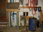
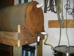
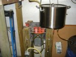
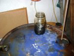
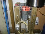
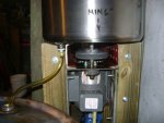
My WMO processing system consists of a settling tank for dirty oil, a 4 stage filtration system, and a cleaned oil storage tank. The oil sits for at least a month in each tank, and I drain off water from them both on a regular basis, so i'm thinking that it's all good, right? The heater mix thing made me a little less sure. So, what to do? I knew that a centrifuge would get the oil cleaner, but the stuff available commercially seemed a bit pricey. So I decided to build one. There is a vid on youtube about a centrifuge made from a torque converter. The torque converter seemed like a good way to overcome the biggest obstacle, a balanced circular form that would hold oil with a rim at the top. So, here we go!! I used materials that have been sitting around literally for decades and now have about $100 tied up in it so far. The 'fuge is a torque converter, the catch basin is a big cooking pot, and the bearings and motor are collected scrap. The biggest expense was fasteners and the wood for the lower half of the stand.

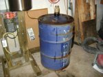
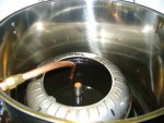
What you see in the pix is a feed tank on the left, the centrifuge in the middle, and the clean tank on the right. The last picture is from spinning up only about 10 gallons of a 50 gallon test run. Testing has been interrupted by knee surgery today, but tomorrow is looking pretty good. Doesn't take much effort to babysit a spinning motor.

Enjoy the pix, and feel free to ask questions. The thing to keep in mind is if I can do it with the limited resources I have, so can you.
 

Attachments

o1951

Active member
899
155
43
Location
Bergen County, NJ
I see you have centrifuge frame solidly bolted to floor.
What is size & RPM of motor?
If I am correct, motor drives a belt to pulley on pillow block, shaft extends thru pot to torque converter.
How did you seal shaft penetration?
How did you mount shaft in tq, and get it all balanced?
Does the shaft have a second bearing?
 

The King Machine

Active member
396
91
28
Location
Vancouver, British Columbia
I see you have centrifuge frame solidly bolted to floor.
What is size & RPM of motor?
If I am correct, motor drives a belt to pulley on pillow block, shaft extends thru pot to torque converter.
How did you seal shaft penetration?
How did you mount shaft in tq, and get it all balanced?
Does the shaft have a second bearing?
That's a good point, the shaft must have a second bearing?
 

Beyond Biodiesel

Active member
373
36
28
Location
Prescott, AZ
Good work. I would only point out that if you blend gasoline with your waste oil as soon as you get it, then leave it to settle for a month, then your settling program will be far more effective.
 

dikwks

Member
237
1
18
Location
Suffolk VA
Thanks for the interest. To answer some of the questions: 1.The keyed sleeve in the center is a coupling from McMaster-Carr. 2.Yes, it is bolted to the floor with anchor bolts. There is enough shake that the whole assembly wants to walk around. I didn't know how wavy my floor was until I set this up. My shims wont stay under it if it walks. 3. The motor is a salvage piece and is really too large for the use but it is what I had. It is a 1hp running at 3450 RPM. I made sure the sheaves were the same size as I wanted the speed of the rotor to be that fast. According to my calculations, it should generate just over 2000G 4. Yes there is a second bearing mounted inside the catch basin. The attachment points for the bearing mount are off to one side because again, it is what I had. A better choice would have been a square mount so the bolts would be symmetrically arranged around the bearing. 5. I didn't seal the bearing, only the mount where it sits in the pot. I am actually hoping for a little bit of leakage through the bearing to keep it lubricated. Otherwise I'll just keep it greased. The oil drains out before it gets high enough to reach the bearing. 6.No I am not either heating or thinning the oil yet. This is still testing so I may yet have to address it.

I have tried as much as possible to use the features already in the converter shell to get my mounting accomplished. The converter originally had a stub on it to center it in the crankshaft. I tried using that to run it, but one episode of vibration ruined it. I needed a better way to mount the rotor so I took piece of plate steel and added the coupling to it. I figured the ends would be square enough to keep the axial runout down. I removed the center of the forward side of the converter so i could use the flat circle made into the shell already to mount the coupling plate combination. I drilled four holes in the bottom of the shell and threaded them and drilled four matching holes in the center plate. I drilled the holes the plate a little large so I could adjust for radial runout. Got the plate centered up with a dial indicator. Ended up with about 15 thou. Welded the plate to the shell so I wouldn't lose the set. The screws work pretty good as a drain. Initially mounted the shell on top of the plate but was too prone to wobble so I flipped it and viola! a pretty steady spin. I am interested to see how well the rotor an the associated welds hold up to the vibration. If they break, no worries, the pot should contain the rotor. I have added the tire weight where it is because it seemed to help a bit, but think I may need to experiment with some larger ones later. For now I'm still making sure the thing will do what I need it to do. Make cleaner oil. The last picture shows some of what I've gotten already, so we may be on the right track.

Enough text for now. I can't type worth beans and my fingers are tired. Check out the pix.
91.JPG92.JPG93.JPG94.JPG95.JPG97.JPG98.JPG
 

glassk

Active member
998
4
38
Location
Hampton, GA
Might need to keep some of the parts in the converter, to control fluid flow , along page 12 has some info some of the shake may be in the fluid entering off center, just 8)
 

Attachments

patracy

Administrator
Staff member
Administrator
14,583
4,604
113
Location
Buchanan, GA
Might need to keep some of the parts in the converter, to control fluid flow , along page 12 has some info some of the shake may be in the fluid entering off center, just 8)
Actually for the centrifuge to function, it needs a collection point as he's got it setup without any obstruction. I'd venture the vibration is due to runout and imbalance. (You'll never get it to completely balance due to the fluid)

I did something similar with a juicer. Unfortunately it is really too small to handle a decent flow rate.
 

dikwks

Member
237
1
18
Location
Suffolk VA
Here's the result of the first run. It ended up being about 40 gallons, it was unthinned and unheated, but had been previously filtered down to 5 microns.
81.JPG82.JPG83.JPG84.JPG85.JPG86.JPG87.JPG88.JPG89.JPG90.JPG

The first three are what I scraped out with my finger, the next ones are how I thinned it with about an ounce of gas and then ran it through a clean cloth. There were small bits stuck to the sides of the jar and the sides of the coffee container. Looks like what was left in the cloth was pieces of filter media. The balls of gunk in the lid felt smooth, but that is to be expected if the particles are 5 microns or lower. I was surprised at the amount of it, I expected more. But abrasive stuff is still abrasive even if it is small, and I will feel better about trying it out in that NHC250 heater. Wonder what would happen with unfiltered oil? Think I'll try that eventually, but for now I am pleased that the centrifuge held up and got it just a little bit cleaner. Edit: took about 8 hours to do the whole run.
 
Last edited:

glassk

Active member
998
4
38
Location
Hampton, GA
Actually for the centrifuge to function, it needs a collection point as he's got it setup without any obstruction. I'd venture the vibration is due to runout and imbalance. (You'll never get it to completely balance due to the fluid)

I did something similar with a juicer. Unfortunately it is really too small to handle a decent flow rate.
Just a thought, the turbine and impeller spinning at close to same speed give a high circular flow , just thinking it may tame the incoming fluid .
guessing about 10 pounds oil and the converter spinning , it's some good fab work and he is having fun it seems with tuning the process.

I like this because I get to learn something new from watching.
 

o1951

Active member
899
155
43
Location
Bergen County, NJ
Looks like you pulled sludge and water out. Be careful exposing your hands to used oil. Read the warning on every container of oil. I got a box of gloves like they use in doctor's/ dentist's office for $5.
 
Top
AdBlock Detected

We get it, advertisements are annoying!

Sure, ad-blocking software does a great job at blocking ads, but it also blocks useful features of our website like our supporting vendors. Their ads help keep Steel Soldiers going. Please consider disabling your ad blockers for the site. Thanks!

I've Disabled AdBlock
No Thanks