• Steel Soldiers now has a few new forums, read more about it at: New Munitions Forums!

  • Microsoft MSN, Live, Hotmail, Outlook email users may not be receiving emails. We are working to resolve this issue. Please add support@steelsoldiers.com to your trusted contacts.


How to bypass PCB? I am aware some HMMWV owners have done it.

TOBASH

Father, Surgeon, Cantankerous Grouch
Steel Soldiers Supporter
3,246
2,955
113
Location
Brooklyn, NY
I'm not trying to speak sacrilege here, and I don't want to precipitate a war of words. :shock:


How might I build a manual control box? My 24Volt Landcruiser just uses a glow wire to show glow plugs are ready, and then she just starts right up with the twist of a key.

Civilian 6.2 Diesel engines don't seem to have a PCB. My slantback is now a personal use vehicle. It is awesome right now but in the future I want to personalize it.

So what needs to be done to bypass and create a working manual "box"? (1987 6.2 with TH400)

(I'm aware of things like overheating and blowing out the glow plugs.)


Best,

T

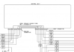
EDIT - post 51 shows schematics as I originally listed them, BUT i decided to post them here on Post #1 to make life easier for the St.So. Family. Happy Independence Day 2022!!!

EDIT - Sept 09, 2023. WARNING! This is a potentially dangerous device that can risk your life and limb. It is not to be taken or undertaken lightly when built or used. Reminder to those who don't read the entire thread... Depressing glow plug button more than 5 continuous seconds or pressing repeatedly may lead to failure and permanent damage. Build at your own risk. I take no responsibility for these plans or anything built utilizing these plans in part or in their entirety. Screwing up the wiring or parts, (or even doing it correctly), can result in catastrophic damage and injury. Even OEM PCB/EESS units have been known to damage vehicles, (including and not limited to those OEM units creating catastrophic damage and fires that risk life and limb and vehicle and surrounding property/structures). This is just posted educational material... It is YOU who takes and assumes all risks, losses and damages, Including but not limited to legal physical financial or anything else. Even OEM PCB/EESS units have been known to damage vehicles, (including and not limited to those OEM units creating catastrophic damage and fires that risk life and limb and vehicle and surrounding property/structures). This is just posted educational material... It is YOU who takes and assumes all risks, losses and damages, including but not limited to physical human damages, legal damages, property damages, life threatening damages, financial damages, and any and all other risk and damages.

1 HMMWV General Electrical Schematic.jpeg2 HMMWV Wiring Instructions Legend.jpeg3 HMMWV PCB Bypass required tools and materials.jpeg4 HMMWV PCB Bypass Schemaic.jpeg
 
Last edited:

TOBASH

Father, Surgeon, Cantankerous Grouch
Steel Soldiers Supporter
3,246
2,955
113
Location
Brooklyn, NY
The following post, reply #21 was AWESOME on how to bypass. Now I need to dream up a schematic with switches that will allow me to activate glow plugs then fire her up AND power electrics.

Best,

T

https://www.steelsoldiers.com/showthread.php?113634-Ever-see-inside-the-Protective-Control-Box


I had a failure of the PCB in my M925A1 last year. As part of the troubleshooting, I made some notes and took some pictures, attached. Mine was the type with a circuitboard. Hopefully the wiring diagrams will be helpful to someone in troubleshooting. I also put together a little troubleshooting guide, which goes to the extent of taking the box apart and checking the individual relays. The relays can be purchased individually fairly economically. In my case the main power relay was bad. I noticed that that model was an Ametek SAS-4418, which is a heavy duty intermittent relay, only rated to be energized 10 minutes at a time. So I replaced it with a SAS-4410, better rated for the application, i.e. continuous duty, more appropriate for the main power relay. Info at texasindustrialelectric.com.


PCB Troubleshooting.docx

As has been noted in other threads, the PCB provides protection against polarity errors and energizing the starter while the engine is running (signal from alternator to Terminal F). In the event of circuitboard failure, it would be pretty easy to rewire the box to bypass the circuitboard and directly energize the relays from the inputs to the box, but then those protections would be gone.


As far as emergency bypassing in the event of failure, you can connect the C & D terminals, the large wires, to replicate the function of the main power relay, then just jumper the starter. You also need to power the fuel solenoid to make the truck run, which can be done with the normal "RUN" switch position on the ignition switch once the main power relay is jumped. Keep in mind that alternator output will go through the jumper so it needs to be substantial. Just for kicks, I made a jumper out of 1/4" steel tubing, stuck it in the PCB plug sockets for Terminals C&D. Ignition switch on, then short the jumper to Terminal B (wire 74) with a screwdriver, the truck fires right up. Just keep in mind the jumper is electrically hot, and be careful handling it especially in the rain; 24 VDC can shock under the right conditions. See picture:


It seems the PCB enclosures may be put together a couple of different ways. I cut mine apart with a thin cutoff wheel in a side-grinder, then tack-welded it at four locations and JB-welded the gap all around.
 

cwc

Active member
Steel Soldiers Supporter
299
138
43
Location
Sweeden, KY
Hi TOBASH, good to hear you found the posting on 5-ton PCBs useful. It is very possible to build a similar box for a HMMWV. A couple of thoughts:

1. Build it so that it uses the existing wiring harnesses and operating switches. Don't make any modifications to the wiring harnesses of the vehicle, keep all of the modifications within the box. This way you can move the box from vehicle to vehicle. You can mount a pushbutton on the box to activate the glowplugs, although it is a little awkward to reach it. You could also make an opening in the box and run a pair of wires out to a switch mounted on the dash.

2. Use a high quality relay to handle the glowplug current. From the texasindustrialelectric.com website, I might think about the SAS-4401 with silver contacts, 200 amp continuous rating, 24 VDC coil. Use flyback diodes on the relays as in the 5-ton boxes.

3. Extra credit: make the Wait light come on as an indicator for when the glowplugs are energized. Note that the Wait light is powered by battery voltage on wire #27 when the Run switch is turned on. So you do NOT want to send the 24 vdc applied to the glowplugs to the Wait light on wire 571; that would have the effect of powering the light from both sides when the glowplugs are on, so the light would go off rather than on. And the glowplugs would be powered through the Wait light (whatever current the light will flow) when the glowplug relay is not energized, and the Wait light will illuminate since it would be grounded through the glowplugs. Hint: use a small relay to provide this function.

Chris
 

TOBASH

Father, Surgeon, Cantankerous Grouch
Steel Soldiers Supporter
3,246
2,955
113
Location
Brooklyn, NY
Hi TOBASH, good to hear you found the posting on 5-ton PCBs useful. It is very possible to build a similar box for a HMMWV. A couple of thoughts:

1. Build it so that it uses the existing wiring harnesses and operating switches. Don't make any modifications to the wiring harnesses of the vehicle, keep all of the modifications within the box. This way you can move the box from vehicle to vehicle. You can mount a pushbutton on the box to activate the glowplugs, although it is a little awkward to reach it. You could also make an opening in the box and run a pair of wires out to a switch mounted on the dash.

2. Use a high quality relay to handle the glowplug current. From the texasindustrialelectric.com website, I might think about the SAS-4401 with silver contacts, 200 amp continuous rating, 24 VDC coil. Use flyback diodes on the relays as in the 5-ton boxes.

3. Extra credit: make the Wait light come on as an indicator for when the glowplugs are energized. Note that the Wait light is powered by battery voltage on wire #27 when the Run switch is turned on. So you do NOT want to send the 24 vdc applied to the glowplugs to the Wait light on wire 571; that would have the effect of powering the light from both sides when the glowplugs are on, so the light would go off rather than on. And the glowplugs would be powered through the Wait light (whatever current the light will flow) when the glowplug relay is not energized, and the Wait light will illuminate since it would be grounded through the glowplugs. Hint: use a small relay to provide this function.

Chris
I'm still a little confused as to where the glowpug power comes from and where to place the wires/switch/button/bypass.

I'm planning on taking a dead PCB and making sure relays work and bypassing the integrated circuit board. I will run wires out of the PCB via a watertight connection.

Yes, relays are KEY. I will use your advice.

If you have a picture of a completed bypass or a schematic of one I would appreciate it. If you could PM me a phone number I would appreciate it. I would like to talk this through.

I'm still in designing phase and it's been a few years since I did this kinda stuff. Spider webs are interfering with brain function.

T
 

TOBASH

Father, Surgeon, Cantankerous Grouch
Steel Soldiers Supporter
3,246
2,955
113
Location
Brooklyn, NY
CWC, your initial post was really awesome! Thanks!

As mentioned above:

I am having trouble figuring out where the glow plug activation and glow plug light functionality are located. I gotta use glowplugs and I would like to use the light. What needs to be done? Which wires are we talking about?
 

Skrilex

Banned
356
2
0
Location
Portland Oregon
My old 6.2 pickup just used a heavy duty momentary switch like for a starter and ran 12v straight to the glow plugs. On warm days you gave it a 5 count on cold days maybe 10. No light no computers nothing. This is how all diesels used to be. My old Mercedes was the same way. Easy, reliable, simple.

Not sure how the troublesome hmmwv setup works but some of the ones with the wait to start light work by measuring resistance which increases as the plugs heat up, that’s why if you have a broken plug that is open the computer will be fooled into thinking they are hot when they are not. You could probably recreate this but, why? With a direct contact like I’m describing you will soon get a feeling for what glow is needed on any given day.

if I were sticking with glow plugs I’d probably do this but my new engine doesn’t have any (thank you Cummins)
 
Last edited:

TOBASH

Father, Surgeon, Cantankerous Grouch
Steel Soldiers Supporter
3,246
2,955
113
Location
Brooklyn, NY
No problem. I had noticed there were no threads detailing this so I made one. I do have to finish it though.
Please do because guys like me could use the insight and help.

Thanks again,

T
 

TOBASH

Father, Surgeon, Cantankerous Grouch
Steel Soldiers Supporter
3,246
2,955
113
Location
Brooklyn, NY
So I still cannot find identification of input and output pins on the PCB boxes. It would be nice to be able to identify what the pins do.

There must be military design specs and such so where are they? Manufacturers would not build stuff without military spec sheets.

The schematics are confusing the heck outa me.

Really I want to identify the glow plug output, the light on/off relays, the starter circuit/relay, and the run/stop circuit/relay.

Seems like the PCB acts like a fuse and circuitbreaker box. I wanna figure out how to reverse engineer an IC free "test box".

Job one - ID all input and output pins ie.: engine side and body side plug pin functions.

Anyone got this info?
 

Wire Fox

Well-known member
1,254
158
63
Location
Indianapolis, Indiana
So I still cannot find identification of input and output pins on the PCB boxes. It would be nice to be able to identify what the pins do.

There must be military design specs and such so where are they? Manufacturers would not build stuff without military spec sheets.

The schematics are confusing the heck outa me.

Really I want to identify the glow plug output, the light on/off relays, the starter circuit/relay, and the run/stop circuit/relay.

Seems like the PCB acts like a fuse and circuitbreaker box. I wanna figure out how to reverse engineer an IC free "test box".

Job one - ID all input and output pins ie.: engine side and body side plug pin functions.

Anyone got this info?
This is basic piece I have right now...

Body side:
A = Neutral safety switch (connector 14B)
B = Master/Start Switch (Run position, connector 29C)
C = Brake warning lamp switch (connector 67A)
D = Ground (connector 57B)
E = WTS Lamp power (connector 571A)
F = Position F on light switch, likely provides power to light switch (connector 15A, looks like it internally connects to G)
G = Master start switch, likely provides power to MSS (circuit 11A, looks like it internally connects to F)
H = 15 Amp CB, provides power to this CB for heater blower circuit (connector 27C)

Engine side:
A = Supply signal to engine components when engine running (connector 54B)
B = Temperature sensor pin 3 (connector 459B)
C = Temperature sensor pin 4 (connector 570A)
D = Glow plug power (connector 575A)
E = 24V supply from batteries (connector 81A)
F = Fan Cutout Switch, Cold Advance Switch, & Alternator Sense (connector 5B)
G = Alternator AC Tap (connector 2A)
H = Temperature sensor pin 1 (connector 573A)
I = Starter relay trigger (connector 74A)

Body A connects to Engine I.
Body B connects to Engine A.
Body F connects to Body G and Engine E.
Body G connects to Body F and Engine E.
Body H connects to Engine F.
The info about these body to engine connections is risky. The drawing warns that this isn't a schematic, but it honestly looks like the drawing is a schematic, but an incomplete one where the all of the non-linked connections are where there is logic decisions being made by the control box.

In all honesty, I just started with the intention to share the picture, but I ultimately stayed for the half hour it took to map everything out. If you can't wire up a bypass with this information at-hand, you're not going to be wiring up a bypass. :lol:
 

Attachments

Last edited:

TOBASH

Father, Surgeon, Cantankerous Grouch
Steel Soldiers Supporter
3,246
2,955
113
Location
Brooklyn, NY
Thanks.

I can put human bodies back together, but that freakin' schematic was killin' me

I think I have a lot to use to make a bypass. I ordered a few dead boxes AND I will start trying to use the plugs to make something we can all use.

You're information is awesome.

Thanks

P.S. I will communicate with you on this project via PM so as not to kill the community with back and forth.

Seems like the computer connections require switches to control functions rather than an internal integrated circuit.

Seems like engine temp feedback stuff can be eliminated.

Seems like glow plug control can be made pushbutton.

Seems like electrical pass throughs for lights and heat can be made into switches.

Need to figure out of anything requires diodes to prevent power back-up.
 
Last edited:

Wire Fox

Well-known member
1,254
158
63
Location
Indianapolis, Indiana
If my hunch is correct on the notation, you can just hard-wire the body to engine connections I mentioned together, disconnect the temp sensor inputs, and wire your push button for the glow plugs onto a relay that's triggered off of Body B and sourced power from engine E. That should make it so that the push button will do nothing if you're not in the "Run" position, to save you from an accidental heating if you bump it or the switch fails. Also thinking further about it, you can probably save yourself from dead batteries due to lights on by using a DPST or DPDT relay and have one pole be for the glow plug circuit and another pole be for the power to lighting. You'd still have some power drawn from the relay being powered on, but it would surely be less than the lights on the truck. I was also thinking of all kinds of other things you could do in there, but then I realized that if we went any farther...you should just install an S3. I haven't put all the brain cells to use on this one to be really sure that this is correct, but I'm sitting right at about 95% certain.
 

TOBASH

Father, Surgeon, Cantankerous Grouch
Steel Soldiers Supporter
3,246
2,955
113
Location
Brooklyn, NY
Stolen from G5o3 and "Fenris"

Many thanks to the poster and the forum there.

Engine Harness
  • Pin A: (output) Feeds fuel injector solenoid, Pin 6 of glow plug controller, Fan temperature switch, Time delay/Engine clutch solenoid
  • Pin B: (input) Pin 3 of glow plug controller (temperature switching feed back)
  • Pin C: (output) Pin 4 of glow plug controller (glow plug heating/timing resistor element)
  • Pin D: (output) Feeds all 8 glow plugs (8 gauge wire required, expected 150 amps)
  • Pin E: (input) Positive battery terminal feed coming off of the starter motor (8 gauge wire required)
  • Pin F: (Bi-directional) Connected to alternator, Sense of alternator, Transmission kick down switch, Cold advance switch (also needed to excite alternator at engine start-up) (8 gauge wire required)
  • Pin G: (input) Alternator A.C. Tap
  • Pin H: (output) Pin 1 of glow plug controller (after glow plug heating/timing resistor element)
  • Pin I: (output) Starter motor starting line
Body Harness:
  • Pin A: (input) Engine start key turned
  • Pin B: (input) Run ignition
  • Pin C: (input) E-Brake warning (break on/off)
  • Pin D: Ground
  • Pin E: (output) Wait to start light
  • Pin F: (output) Power feed to all turn signal, head lights, and horn (connected directly to battery feed on engine harness pin E)
  • Pin G: (output) Power feed to the ignition key switch (connected directly to battery feed on engine harness pin E)
  • Pin H: (output) Power feed to internal cab heating fan (active when run ignition is live)
 
Last edited:

TOBASH

Father, Surgeon, Cantankerous Grouch
Steel Soldiers Supporter
3,246
2,955
113
Location
Brooklyn, NY
So how do we get the schematic diagrams AND integrated circuit board pics from the manufacturers? Where do we get the military technical specs for how a PCB is supposed to operate? Is this a "Freedom of Information" thing OR is there a department within the DoD we can write to? Will the manufacturers answer questions?

I will try to reverse engineer a simple IC free unit BUT if there is information out there for the taking, that might be preferable.

T
 

TOBASH

Father, Surgeon, Cantankerous Grouch
Steel Soldiers Supporter
3,246
2,955
113
Location
Brooklyn, NY
I'm beginning to think I also need an old Prestolyte box for evaluation.

Is there a vendor here with one?

EDIT - Found a dead one and bought it. More would be better to compare live and dead parts.
 
Last edited:

TOBASH

Father, Surgeon, Cantankerous Grouch
Steel Soldiers Supporter
3,246
2,955
113
Location
Brooklyn, NY
Essentially, the more I dissect the more interesting this thing gets.

Essentially the PCB is a decision engine.

If glowplugs are OK, a decision is made to power them up. If they power up properly, a decision is made to allow the starter solenoid to engage. At the same time a decision is made to power the fuel pump. A decision is also made to provide power to electrics like heating, lights, etc...

ALL of this can be bypassed with switches, and diodes can prevent feedback.

Wires from the plugs enter the IC board. The IC board then has exiting wires to the relay or to the other plug. Some wires pass through the relay to the other plug. Others pass through the IC to the same plug. The PCB is reading glow plug temps and currents and making decisions based on glowplug temps and continuity. Must of the engine sided wires are dealing with plugs sensors and heat sensors. Really, only the glow plug power up wires are essential. There are a few wires going from the body side to the IC board, but those seem to deal with activation of glow plug timer and such, and don't seem essential. Most importantly, the only high power wires going in and out of the system seem to be activated by one small wire from the IC board to the main relay low power wire.

In the KDS "Green Label" box, and the Nartron White label "Smart Box" and Nartron "Yellow Label" box, there is a single wire to activate the main relay. That implies that powering up a dead vehicle that won't turn over requires activation of one simple wire to activate electrics and power up the starter solenoid!

In the KDS "Smart Box" there are a mess of relays and a confusing IC board so that seems more complex. That being said, if the KDS SmartBox has separate relays for each function, it is simple to create a low voltage switch to each relay. Pushbutton switch to glow plugs and toggle switch to the others. Starter seems to have it's own circuit that might also need a pushbutton. I will need to purchase a dead KDS "SmartBox" because mine is good and I don't wanna kill an expensive item.

Ultimately, I'm beginning to wonder if creating a separate glow plug unit and then just powering up the low power wire to the PCB main relay will activate the system and bypass all the complicated PCB electrics. Fuses can protect the circuits, or circuit breakers might be even better. Running small 24V led lights in parallel with the glow plugs will identify bad plugs at a glance. For extra credit I guess you could run wires to the dash with a small box and labeled LED's for each plug.

If all this is as simple as running a pushbutton activated low power wire to a relay activating the glow plugs, and running a separate low voltage wire and switch to the dead box' low power relay activation wire, I will crap myself.

T

EDIT, Starter wires go from body plug to IC to engine plug. Easy to connect them with a switch but given starter position on the "key" is spring loaded, it seems that they can just be jumpered to eachother.
 
Last edited:

cwc

Active member
Steel Soldiers Supporter
299
138
43
Location
Sweeden, KY
So how do we get the schematic diagrams AND integrated circuit board pics from the manufacturers? Where do we get the military technical specs for how a PCB is supposed to operate? Is this a "Freedom of Information" thing OR is there a department within the DoD we can write to? Will the manufacturers answer questions?
There is some information in patents as described in thread "PCB circuit diagram of KDS controller":

https://www.steelsoldiers.com/showthread.php?115247-PCB-circuit-diagram-of-KDS-controller

I described what I found internally in a particular Nartron yellow-label box here in thread "M998--new glow plugs burnt out and swollen in 2 hours".

https://www.steelsoldiers.com/showt...-plugs-burnt-out-and-swollen-in-2-hours/page2

The wiring diagram in the TMs also gives some insight into the intended functionality. Note that above the PCB it says "Logic representation only - not a schematic".
 

TOBASH

Father, Surgeon, Cantankerous Grouch
Steel Soldiers Supporter
3,246
2,955
113
Location
Brooklyn, NY
There is some information in patents as described in thread "PCB circuit diagram of KDS controller":

https://www.steelsoldiers.com/showthread.php?115247-PCB-circuit-diagram-of-KDS-controller

I described what I found internally in a particular Nartron yellow-label box here in thread "M998--new glow plugs burnt out and swollen in 2 hours".

https://www.steelsoldiers.com/showt...-plugs-burnt-out-and-swollen-in-2-hours/page2

The wiring diagram in the TMs also gives some insight into the intended functionality. Note that above the PCB it says "Logic representation only - not a schematic".
Amazing post AND seems to confirm my suspicions about function AND bypass!

Many thanks!
 
Top
AdBlock Detected

We get it, advertisements are annoying!

Sure, ad-blocking software does a great job at blocking ads, but it also blocks useful features of our website like our supporting vendors. Their ads help keep Steel Soldiers going. Please consider disabling your ad blockers for the site. Thanks!

I've Disabled AdBlock
No Thanks