Mtour
New member
- 3
- 0
- 1
- Location
- Nova Scotia
Hey Guys I have purchased a mep-831a with a tier two reset with 7hrs showing on it, the circuit interrupter will only work in battle short. The governor control module is shot, I have one of Kurts boards on route to solve that. I was able to get a stable 240vac measured at the inverter with no warning lights from the unit at no load by disconnecting the governor control module and using a elastic band on the governor linkage to achieve 178vac at a-b terminals.
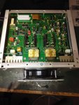
I traced the ground circuit to the inverter to connector p17-11, but I do not get continuity between terminal p17-11 and p17-12. My understanding is that P17-11 goes to relay k8 which is normally closed and continues to p17-12 and then on to the battle run switch.
This is leading me to think that the K8 relay inside the inverter is faulty.. I am I on the right track here, and if so has anyone done a relay swap on the K8 relay..
Thanks
Dave