• Steel Soldiers now has a few new forums, read more about it at: New Munitions Forums!

  • Microsoft MSN, Live, Hotmail, Outlook email users may not be receiving emails. We are working to resolve this issue. Please add support@steelsoldiers.com to your trusted contacts.


More Alternator/Electrical Questions

AZDeuce

Active member
484
38
28
Location
Tonopah, AZ
A couple weeks ago my Gen 1 light came on while driving, a little research in the CUCV forums showed me this was not a good thing.

After reading and hard copying many different posts, I decided to order two heavy duty 27 SI rebuild kits.

I disconneted the battery, removed and rebuilt Gen 1. Opening up my kits I found neither one had the Trio-diode, a quick call straightened that all out, but did me no good at the moment, so I istalled all the new parts plus my old trio-diode.

I reinstalled it, and the Gen 1 light came on when I turned the key on, but went out immediately after the engine started, and stayed off during a short around the block drive.

Mongo HAPPY!

Aw, but not so quick.......

A day later while driving to work, the GEN 1 light came on and stayed on, then pretty soon just for about a few seconds I smelled something electrical hot or burning.

But then it quit - I'm ASSuming that the "magic smoke" came out of something.....BUT WHAT?

I've always been electrically challenged, but I thought armed with all the knowlege on this site, that I'd hard copied and read over several times, that I could figure it out.

So yesterday, I bought a Multimeter from Lowes, and this morning sallied forth to wage war on the electrical gremlin that is the CUCV.

But alas, I'm still electrically challenged even with my new multimeter. The CUCV is kicking my butt.

Here's what I got so far.

Battery 1 has 12.30V
Battery 2 has 12.57V

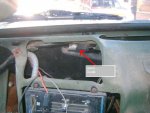
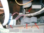
Testing the dual wired plug on the alternator w/one red & one brown wire:

With the ignition OFF

Gen 1 Red = 12.28V
Gen 2 Red = 24.8V

Wih the ignition ON

Gen 1 Brown = 11.41
Gen 2 Brown = 0

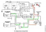
So I tried to make sense of the skematic/diagram I found on one of the posts I copied but the brown wire goes to some kind of box.......but the box has no name.

What is it that I'm looking for to find the other end of the brown wire for Gen 2?

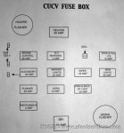
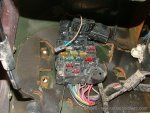
I pulled all the fuzes out of the fuze box and they're all ok, but one of the posts mentioned a 24V fuze at the very bottom of the fuze box, my fuze box has NO fuzes on the bottom row.

Am I missing a fuze?

Inspite of the fact I have a multimeter I still don't have a clue what I'm doing, or how to look for it.

HELP!! (Please)

Can somebody take pity on this electically challenged CUCV owner, so I can get her back on the road?
 

Barrman

Well-known member
5,153
1,556
113
Location
Giddings, Texas
Page 275 of the -20 has a diagram with sub notes about what goes where in the fuse panel.

Does your voltage meter in the dash work?
 

Warthog

Moderator
Super Moderator
Steel Soldiers Supporter
13,775
227
63
Location
OKC, OK
The brown wire on GEN2 goes to the GEN2 relay under the ashtray. The relay and the brown wire require 24v from the very bottom 24v fuse.

Has the GEN2 light ever come on? Both GEN1 and GEN2 lights need to come on when the key is first truned on and then go out when the engine is started.

Here is a diagram of the GEN2 "brown" excitor wire. I changed the color to green to make it easier to follow.

Here is the path:

24v fuse to pin #3 on the instrument cluster (orange wire)
pin #3 thru the GEN2 idiot light to oin #4 on the instrument cluster
pin #4 to the GEN2 relay (red wire)
GEN2 relay to the GEN2 diode above the heater control
GEN2 diode to the large firewall plug
firewall plug to the GEN2 pin#1

Each of the parts need to be working. You need a fuse, working bulb and clean connections.

Make sure you read the first couple of pages of the Troubleshooting Section of TM 9-2320-289-20. It will help explain how to read and troubleshoot the wiring diagrams.
 

Attachments

Last edited:

Warthog

Moderator
Super Moderator
Steel Soldiers Supporter
13,775
227
63
Location
OKC, OK
There are hundreds of videos on Youtube on how to work a voltmeter

[media]http://www.youtube.com/watch?v=LPaTsBrd-Tg&feature=related[/media]
 

AZDeuce

Active member
484
38
28
Location
Tonopah, AZ
Thanks for the help, that was the scematic I was looking at, but couldn't figure out what the box was that the brown wire (which I assume is the "excitor" wire) went to. Maybe with your description I'll figure it out.

My m1009 does not have the volt meter, I think that belongs up on the top right hand side of the dash panel, mine has a switch for the A/C unit installed by our Sheriff Dept before I got it,

I don't remember if the Gen 2 light ever came on or not, but I know it doesn't now.

Hopefully that -20 manual is in the resourse section, as I have no manuals for this beast except a Chilton civilian manual.

I need to see where that bottom 24V fuze goes. I noticed a loose 30A fuze lying on the drivers side floor, I carry spare fuzes under the driver's seat, and just figured it was one that got loose. But I drive it with my work boots on, and now I'm wondering if I kicked the fuze out of the holder?

I'll try to figure out the fuze issue first as it sounds like that would interfer with not getting power to the brown wire on Gen 2.

Is that a reasonable plan?
 

Warthog

Moderator
Super Moderator
Steel Soldiers Supporter
13,775
227
63
Location
OKC, OK
All of the manuals are in the Resources section on the old website.

You can look them up or they are linked on the Wiki page

Cucv Wiki - Steel Soldiers::Military Vehicles Supersite

If the Sheriff's Department added A/C, then they may have disconnected the GEN2 system.

Post some pictures of the engin compartment, especially the alternators and battery wiring and the dash area.

This may take awhile to figure out.
 

AZDeuce

Active member
484
38
28
Location
Tonopah, AZ
Warthog

Unfortunately I am digitally challenged when it comes to posting pic.....I only have dial up webtv (yeah, I know I'm living in the stone age) I will try toget some photos and see if my nephew can down lod them to my e-address, and I can send them direct to you.

I'll give you a shout (PM) if I can get that much accomplished.

Thanks for your help/concern
 

mistaken1

New member
1,467
6
0
Location
Kansas City, KS
If Gen 2 red is 24V then the starting system is still probably 24V. That fuse you found on the floor may very well be your 24V fuse.

Draw pictures. Draw lots of them, they are invaluable in helping you see what is going on.

Draw a picture of all of your wiring related to the batteries and alternators (based on what you physically trace out by hand).

Take voltage readings at all the terminals you can access and mark on your drawing where you took the reading and what voltage you got (terminal to ground, ideally the negative of the front battery). You can do this for key on and key off.

Then compare what you draw with what Warthog posted.

You can scan your drawings and post them or take a good clear digital photo of them and post them. A picture is worth a thousand words.
 

wallew

Active member
Steel Soldiers Supporter
2,520
18
38
Location
San Angelo, Tx USA Planet Earth
That 30 amp fuse is CRITICAL to your system. Make sure you use a clean fuse and that the spot it goes into is also clean.

I had that fuse pop in one of my vehicle. Once I figured it out and cleaned it up, my problem was resolved.

So check that 30 amp fuse and replace it.
 

AZDeuce

Active member
484
38
28
Location
Tonopah, AZ
Cool! I'll check the fuze first thing. I looked at the -20 manual in the SS Resources section, and found a picture (drawing actually) of the fuze box, it only shows ONE fuze location at the bottom of the fuze box, mine has THREE!

What in the World!!??

My truck came 2nd hand from our Sheriff Dept who put A/C in her, did they change out the fuze box or did chevy use different fuze boxes at different times?

SO.........my question is......Can I just start sticking the probes of my multimeter in those three slots until I find the one that is 24V?

And if so, Do I ground the one probe against the truck some where, while I probe the fuze holes with the red wire, or do I stick both probes in the hole one on each metal connection?

I'm guessing I want my multimeter grounded out on the truck somewhere, but being new at this I don't want to burn up my meter, nor do want to miss finding the 24V fuze location, so someone let me know what to do.

By the way THANKS for all the help so far, hopefully when this is done, I'll have a better understanding of how to trouble shoot vehicle electrical problems, right now I'm afraid I might burn her to the ground.
 

Warthog

Moderator
Super Moderator
Steel Soldiers Supporter
13,775
227
63
Location
OKC, OK
On your multimeter you ground the black wire to the body of the truck. I good place is one of the screws holding the metal sill plate. Then probe the fuse box with the red wire/lead.

The is a picture of the stock fuse box from the CUCV FAQ thread sticky

http://www.steelsoldiers.com/233428-post15.html

Since you can't take any pictures, compare what you have to the picture. Someone could have replaced the fusebox.
 

Attachments

AZDeuce

Active member
484
38
28
Location
Tonopah, AZ
Warthog

I did manage to get some pictures yesterday, my nephew down loaded them and sent them to my address, but I got only text and no pictures, he said he'd try again, but hasn't as of yet.

I'll check my fuze box against your picture, but I'm pretty sure mine is different. I'll let you know as soon as can check it out (I'm at work now)
 

1008Newbie

New member
20
0
1
Location
Greenfield, IN
Just hold the black probe on some bare metal or bolt which should be grounded and you can probe all day long with the red probe and not hurt anything as long you have the meter on "volts" and you only touch one piece of metal with the red probe at a time.

I had electrical gremlins on my truck and it was a rusty ground bolt where Gen1 Ground wire meets the intake manifold. Thats probably not your issue, but figured I'd mention it anyway since it took me a while to find that problem on my m1008. Good luck!
 

AZDeuce

Active member
484
38
28
Location
Tonopah, AZ
It's been a hectic week, but FINALLY I got to spend about an hour with my M1009.

I checked the bottom fuse hole with the multi meter (MM) and sure enough there was 24V on the one side, so I stuck a 10 amp fuse in the hole. I then turned on the key, put the multimeter on Gen 2's Brown wire, and got I think around 12.V something or the other.

Earlier I had nothing on that wire, before I inserted the fuse. Thats as far as I got before I got interupted, but I did start the truck and the gen 1 light went out (#2 light never did come on)

I went to go get some readings of it running, with the MM, and saw that I'd forgot to plug in the dual plug w/the red and brown wire on Gen 2 so I plugged that in, while it was still running, then I checked my dash lights and # 1 was just barely glowing, and that's when I got interupted so I have no readings of it running.

But maybe I can get some before it gets dark.

So it seems to have "gotten better" in that the GEN 1 light is not on bright when the truck is running, but there is a soft glow while it idles, but when I advance the throttle, the light goes out.

To my way of thinking that may be a good sign, but that just may be wishful thinking on my part.

But adding that fuse back into the equation sure seemed to change things.......possibly for the better. Time will tell.
 

AZDeuce

Active member
484
38
28
Location
Tonopah, AZ
OK, I went outside and fire her up and here's the readings I got with her running:

Btry 1..............................................11.97
Btry 2...............................................14.?

Gen 1, Red wire..........................11.97
Gen 1, Brown wire..........................? (couldn't get to it due to the bracket over it)

Gen 2, Red wire..........................26.6
Gen 2, Brown wire.....................26.6

I'm guessing that since I have a dim Gen 1 dash light, and I only get 11.97 readings off of the gen 1 Red wire, and the #1 battery, that Alt #1 isn't charging, and what I'm reading is the Volts coming from the battery.

Would this be a correct assumption?

Since I already rebuilt the alternator last week, but reused the old trio-diode as the new ones weren't in the package), should I open her back up and install the new trio-diodewhich finally showed up?

What says you all?
 

Barrman

Well-known member
5,153
1,556
113
Location
Giddings, Texas
Yes, you seem to have narrowed it down to alt 1. Pull the alternator apart and do the checks in the -34 manual of each component inside the alternator.
 
Top
AdBlock Detected

We get it, advertisements are annoying!

Sure, ad-blocking software does a great job at blocking ads, but it also blocks useful features of our website like our supporting vendors. Their ads help keep Steel Soldiers going. Please consider disabling your ad blockers for the site. Thanks!

I've Disabled AdBlock
No Thanks