I figure I would post this in case someone like me wants to use a double pole rocker switch to manually control their fan clutch based on
@Mogman excellent drawing.
Like Mogman indicated, I ran three 18 guages wires under one jacket into the cab.
I used a "Waterproof Rocker Switch Toggle On-Off-On 12V/20A 24V/10A 7Pin DPDT Blue LED Light" that is standard for rocker switch panels.
I was a bit picky, and wanted the middle position, normally called "off" to let the thermo switch on the engine to control the fan clutch. So I used a relay to enable this as shown.
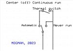
On the drawing below:
- Disconnect both packard connectors from the thermo switch and use a VOM to detmine which lead from the Cadillac valve has 24V present with the ignition on. This is the lead that needs to be "cut". Actually, I used extra packard connectors to build the leads so I could put the wiring back anytime in the future.
- I am showing the back of the rocker switch. There are two rows of pins. With the switch oriented "up", the row on the left has 3 pins.
- The middle pin in the left row needs to have the 12 or 24V+ (ignition) source.
- The right row has four pins.
- The upper pin on the right row is ground for the internal LED light on the switch.
- The upper position of the switch activates "Continuous" engaged clutch. The upper led light on the switch will turn on.
- The middle position of the switch, normally called "off" is Automatic mode, and lets the Thermo Switch on the engine. No light on the switch us illuminated.
- The lower position of the switch is clutch "disengaged" mode. The bottom led light on the switch will turn on.
- The pins are upside down, so when the switch is toggled up, the pins on the bottom make the circuit, and visa-versa. Use a VOM to verify.
- You need a DPST 24 or 12V relay. Don't try to use a 24V relay if you are using 12V source as the relay probably will not work right.
- If you have AC, you can tap into the AC on source, but use a diode to prevent a back feed to your AC systenm when you have the fan clutch switch in the upper position. Make sure the band on the diode is towards the switch, point away from your AC.
Hope this helps someone. Thanks to
@Mogman for making the circuit function so clear
")