- 1,311
- 1,687
- 113
- Location
- Basehor, KS
pf.hal1984
Please check the resistance of your exciter coil in the genhead first
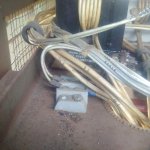
a) Locate this barrier terminal strip with two positions:

locate and remove wire F1 and F2 - check ohm between these two - should be between 1 to 4 ohm
remember which F wire goes to which terminal
then proceed as follows:
b. Equipment Test of Field Flash Circuit Assuming the exciter stator winding resistance is correct (within 1 to 4 ohms)Connect a DC voltmeter (0 to 30 volts) to the two wires that are disconnected from the exciter stator windings. NOTE DO NOT reconnect the wires to leads F1 and F2 at this time.
c. Remove Connector P37 from speed switch. Place a jumper between pins A and C on P37. Momentarily,approximately 10 to 15 seconds, place the START-STOP-RUN switch in the START position and observe the DCvoltmeter. If the voltmeter indicates approximately 24 volts, the probable cause of the field flash is the speed switch. If aDC voltmeter is not available, proceed to step d.
d. Remove Connector P3 from the speed switch. Place a jumper between pins A and C of socket J3 on the specialrelay box for approximately 24 volts DC. If a DC voltage is not present, the problem may be the wiring between the speedswitch and the special relay box, the K5 relay, or current limiting resistor (R35) inside the special relay box (15kW and 30kW generator sets only). If a DC voltage is present, replace Connector P3 on socket J3 and proceed to the next step.
e. Remove Connector P9 from the static exciter/voltage regulator control box. Momentarily, hold the START-STOPRUNswitch in the START position and check between pins C and D of P9 for approximately 24 volts DC. If a DC voltageis not present, the problem may be the wiring between the special relay box and the static exciter/voltage regulator controlbox. If a DC voltage is present, replace Connector P9 on-socket J9 and’ proceed to the next step.
f. Remove Connector P13 from the static exciter/voltage regulator control box. Momentarily, hold the STARTSTOP-RUN switch in the START position and check between pins S and R of J13 on the control box for approximately 24volts DC. If a DC voltage is not present, the problem may be any one of the following items within the control box:
(1) Broken wire within the control box.
(2) Current limiting resistor R219 sets.
(3) Current limiting resistor R17 sets.
g. Reconnect the wires previously removed from the exciter field winding, F1 and F2.
Please check the resistance of your exciter coil in the genhead first
a) Locate this barrier terminal strip with two positions:

locate and remove wire F1 and F2 - check ohm between these two - should be between 1 to 4 ohm
remember which F wire goes to which terminal
then proceed as follows:
b. Equipment Test of Field Flash Circuit Assuming the exciter stator winding resistance is correct (within 1 to 4 ohms)Connect a DC voltmeter (0 to 30 volts) to the two wires that are disconnected from the exciter stator windings. NOTE DO NOT reconnect the wires to leads F1 and F2 at this time.
c. Remove Connector P37 from speed switch. Place a jumper between pins A and C on P37. Momentarily,approximately 10 to 15 seconds, place the START-STOP-RUN switch in the START position and observe the DCvoltmeter. If the voltmeter indicates approximately 24 volts, the probable cause of the field flash is the speed switch. If aDC voltmeter is not available, proceed to step d.
d. Remove Connector P3 from the speed switch. Place a jumper between pins A and C of socket J3 on the specialrelay box for approximately 24 volts DC. If a DC voltage is not present, the problem may be the wiring between the speedswitch and the special relay box, the K5 relay, or current limiting resistor (R35) inside the special relay box (15kW and 30kW generator sets only). If a DC voltage is present, replace Connector P3 on socket J3 and proceed to the next step.
e. Remove Connector P9 from the static exciter/voltage regulator control box. Momentarily, hold the START-STOPRUNswitch in the START position and check between pins C and D of P9 for approximately 24 volts DC. If a DC voltageis not present, the problem may be the wiring between the special relay box and the static exciter/voltage regulator controlbox. If a DC voltage is present, replace Connector P9 on-socket J9 and’ proceed to the next step.
f. Remove Connector P13 from the static exciter/voltage regulator control box. Momentarily, hold the STARTSTOP-RUN switch in the START position and check between pins S and R of J13 on the control box for approximately 24volts DC. If a DC voltage is not present, the problem may be any one of the following items within the control box:
(1) Broken wire within the control box.
(2) Current limiting resistor R219 sets.
(3) Current limiting resistor R17 sets.
g. Reconnect the wires previously removed from the exciter field winding, F1 and F2.


