• Steel Soldiers now has a few new forums, read more about it at: New Munitions Forums!

  • Microsoft MSN, Live, Hotmail, Outlook email users may not be receiving emails. We are working to resolve this issue. Please add support@steelsoldiers.com to your trusted contacts.

MEP-804B Problem Starting

Rik

Member
36
24
8
Location
California
The people here in the forum simply encourage others to become more knowledgeable about their own equipment. It goes without saying that the more time you spend with your own head in those tight places you were referring to, the more efficient you will get in the trouble-shooting process. This is better than someone telling you what might be the culprit, because by nature we learn more in the hands on approach. As was previously mentioned in this thread, every wire, cable and component is clearly labeled in the schematics and on or near the physical wire, cable or part in the unit. This is one of the main things that attracted me to them in the first place. They’re very simplistic.

What you’re dealing with on your unit is otherwise known as “a voltage drop.” You may see the correct voltage as measured in a specific place with a volt meter. But as soon as a load is applied the voltage either drops very low or it goes away completely. The J5/P5 and/or the J6/P6 connectors on these machines are known to be one cause of the voltage drops that you’re dealing with. As others have already suggested, I will echo them and urge you to read, study and then apply that to what you see in front of you. I’m sorry that your unit is not at your primary residence for convenience.
I see you seem to like OJT, but if you knew the answer and withhold it then what’s the point of these forums? It’s not a treasure hunt, it’s a problem that I need an answer to. Simple, uncomplicated and easy for someone to pass along to others in need.
 

Rik

Member
36
24
8
Location
California
What you’re dealing with on your unit is otherwise known as “a voltage drop.” You may see the correct voltage as measured in a specific place with a volt meter. But as soon as a load is applied the voltage either drops very low or it goes away completely. The J5/P5 and/or the J6/P6 connectors on these machines are known to be one cause of the voltage drops that you’re dealing with. As others have already suggested, I will echo them and urge you to read, study and then apply that to what you see in front of you. I’m sorry that your unit is not at your primary residence for convenience.
Thank you for the tip, I’ll read the manual in reference to these J5/P5 and J6/P6 connectors
 

Guyfang

Moderator
Staff member
Moderator
16,784
24,129
113
Location
Burgkunstadt, Germany
To check MT4, measure from the right side of MT4 to ground. Should be 24 VDC. Then measure from the left side of MT4 to ground. Should be 24 VDC. Look straight down at MT4, from above. In the middle looks like a fuse-able link. And yes boys and girls, that is what it is more of less. If there is a gap in the link, its bad.

You mean FU1? FU2 is for the Quad Circuit protection.

Testing FU1 is simple. Test to one output lead, to ground. Then to the input lead to ground. 24 VDC both sides then the fuse is good. You can test the fuse also, ohms, but I have been fooled several times by a fuse that is bad, and still ohms out good. Its a break in the fuse-able thread in the fuse. Its broken, but still making contact. In such a situation, it can read good, but pass no current.
 

Rik

Member
36
24
8
Location
California
To check MT4, measure from the right side of MT4 to ground. Should be 24 VDC. Then measure from the left side of MT4 to ground. Should be 24 VDC. Look straight down at MT4, from above. In the middle looks like a fuse-able link. And yes boys and girls, that is what it is more of less. If there is a gap in the link, its bad.

You mean FU1? FU2 is for the Quad Circuit protection.

Testing FU1 is simple. Test to one output lead, to ground. Then to the input lead to ground. 24 VDC both sides then the fuse is good. You can test the fuse also, ohms, but I have been fooled several times by a fuse that is bad, and still ohms out good. Its a break in the fuse-able thread in the fuse. Its broken, but still making contact. In such a situation, it can read good, but pass no current.
I measured across the lugs on the MT4 and there is in fact 25V on each when measured. I never could see if the link between them is good so today I just ordered a new MT4 as it's less expensive to change out the possibilities all at once than it is to drive back and forth and waste gas as it's a $60 round trip tax to the pumps each trip. I use this generator to power my remote business location as the building does not have 440V 3 phase power and down time is costly especially when I'm chasing more than catching.

I'm searching for a new breaker as well as for the cost it's quicker and easier to just replace and know that possibility is eliminated. Replaced a perfectly good S1 switch last week with this thinking but I know it's not that after the switch.

Can you please tell me which TM has the wiring diagram? I've downloaded Tm24 and I cannot find it on any page. I used the diagram on the generator doors when I am in front of the machine but that's of no use once I leave the machine.
 

loosegravel

Just a retired mechanic who's having fun!
504
892
93
Location
Enumclaw, Washington
I measured across the lugs on the MT4 and there is in fact 25V on each when measured. I never could see if the link between them is good so today I just ordered a new MT4 as it's less expensive to change out the possibilities all at once than it is to drive back and forth and waste gas as it's a $60 round trip tax to the pumps each trip. I use this generator to power my remote business location as the building does not have 440V 3 phase power and down time is costly especially when I'm chasing more than catching.

I'm searching for a new breaker as well as for the cost it's quicker and easier to just replace and know that possibility is eliminated. Replaced a perfectly good S1 switch last week with this thinking but I know it's not that after the switch.

Can you please tell me which TM has the wiring diagram? I've downloaded Tm24 and I cannot find it on any page. I used the diagram on the generator doors when I am in front of the machine but that's of no use once I leave the machine.
I take it this unit is not trailered. Any way for you to load it up onto a flatbed trailer so you can haul it home with you to repair it there? It may prove to be less costly than spending money on gas going back and forth while also spending money replacing otherwise good parts.
 

Rik

Member
36
24
8
Location
California
I take it this unit is not trailered. Any way for you to load it up onto a flatbed trailer so you can haul it home with you to repair it there? It may prove to be less costly than spending money on gas going back and forth while also spending money replacing otherwise good parts.
No I store it inside my shop at the door so that the exhaust goes out the bay door and it stay's safe and dry no matter what the weather is like.

I could load it into the back of my truck and bring it home as it will fit with the tailgate up in a 6.5' truck bed but I think I can get this now with all the help that I have received.

I understand what your saying with the voltage drop as when I measure the leads on items (such as the S10, MT4 etc.) there's 25V but when I turn that switch on the voltage drops to like 7V so there's to much resistance in the line for some reason.

I've tested continuity and it test out on these wires but when it's time to carry the power it does not want to work. Thus why I jumped the S10(2) wire to a known 25V power source and then magically everything was back to normal. So my plan, since it cost less than $100.00 to do this, is to replace the MT4 and the FU2 on the inside of the panel cabinet and see if the problem is cured. I checked the cannon plugs J&P 5&6, and they were tight as well as spotless clean on the terminals. I am also considering replacing K2 just to certain that there's nothing left in this line to cause the problem as when I checked continuity between K2(X1) and S10(1) there was continuity but when I jumped the wires from S10(1) to K2(A1) the engine would not crank. I believe that's the wires I was messing with.

For me, this unit is a work item as I needed 440V 3 phase for work and this unit can produce the power with no problems and I can switch it down to 220V as well (although I wish I didn't have to stop and switch between my machines) when needed between them. This is why I asked questions as I need this to work or I'm at a stopping point. Luckily Peter knew enough about these units to help me isolate the source of the failure point and then progress from that point forward.

Thank you too!
 

peapvp

Well-known member
Steel Soldiers Supporter
1,118
1,240
113
Location
Basehor, KS
when I checked continuity between K2(X1) and S10(1) there was continuity but when I jumped the wires from S10(1) to K2(A1) the engine would not crank. I believe that's the wires I was messing with.
for clarification:
@Rik made a jumper wire from S10(1) to K2(X1) first to check this connection
S10(2) showed 25V on meter
then he pushed S10 to crank and no crank and Voltage on S10(2) dropped from 25V to around 7V
S10(2) is the 24V supply which is toggled by S10 between crank test and normal meaning supplying 24VDC to cubicle
when @Rik applied a jumper wire directly from a good known source of 24V to S10(2) and put S10 into normal position then he was able to start run power stop Genset as usual

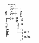
S10(2) is the com contact and wire 163D connects to MT4(1) and from there to FU1(1)

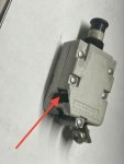
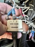
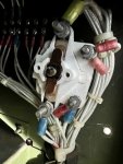
FU1 is a 25A DC Circuit Breaker
we have encountered several of these type of dc circuit breakers causing problems due to old age.


70189612565__38E6F8C6-7997-47B5-B009-95C1CEDC7F49.jpeg

The one leg starts to make a poor contact internally increasing Resistance between both legs. Eventually this one leg just breaking off due to vibration.

we have found this issue on both 7.5A and 25A breakers

the MT4 issue as described by @Guyfang I have not seen yet, but I am sure it’s lurking out there
 
Last edited:

loosegravel

Just a retired mechanic who's having fun!
504
892
93
Location
Enumclaw, Washington
for clarification:
@Rik made a jumper wire from S10(1) to K2(X1) first to check this connection
S10(2) showed 25V on meter
then he pushed S10 to crank and no crank and Voltage on S10(2) dropped from 25V to around 7V
S10(2) is the 24V supply which is toggled by S10 between crank test and normal meaning supplying 24VDC to cubicle
when @Rik applied a jumper wire directly from a good known source of 24V to S10(2) and put S10 into normal position then he was able to start run power stop Genset as usual

S10(2) is the com contact and wire 163D connects to MT4(1) and from there to FU1(1)

FU1 is a 25A DC Circuit Breaker
we have encountered several of these type of dc circuit breakers causing problems due to old age.


View attachment 895267

The one leg starts to make a poor contact internally increasing Resistance between both legs. Eventually this one leg just breaking off due to vibration.

we have found this issue on both 7.5A and 25A breakers

the MT4 issue as described by @Guyfang I have not seen yet, but I am sure it’s lurking out there
The truth is, there’s a simple loose connection or corroded connection somewhere causing the voltage drop on the 163 24vdc circuit for the main panel. I believe that it begins on the large 24vdc connection on the starter, then it goes to the s10 switch. It will show itself very soon! Just for the sake of troubleshooting, I would put a 3/4” socket on the starter main 24vdc stud and give it a tweak.
 

peapvp

Well-known member
Steel Soldiers Supporter
1,118
1,240
113
Location
Basehor, KS
@loosegravel, that was my thought as well.
@Rik jumped K2(X1) to K2(A1) and that resulted in cranking.
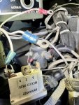
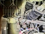
Rik said after taking ring terminals off the terminals that there was no sign of corrosion or oxidation


IMG_1122.jpeg

IMG_1133.jpeg
IMG_1106.jpeg
IMG_1117.jpeg

so he started to investigate the Amphenol Connector
and that leaves us at the moment with MT4 and FU1 as suspect
i was not able to see any clear signs of corrosion in the pictures @Rik had texted me and as far as I know he did not encounter any loose connections but I am not sure on how far @Rik has checked for that particular issue
 

Guyfang

Moderator
Staff member
Moderator
16,784
24,129
113
Location
Burgkunstadt, Germany
No I store it inside my shop at the door so that the exhaust goes out the bay door and it stay's safe and dry no matter what the weather is like.

I could load it into the back of my truck and bring it home as it will fit with the tailgate up in a 6.5' truck bed but I think I can get this now with all the help that I have received.

I understand what your saying with the voltage drop as when I measure the leads on items (such as the S10, MT4 etc.) there's 25V but when I turn that switch on the voltage drops to like 7V so there's to much resistance in the line for some reason.
(When a wire is broken, or almost broken, it will pass an ohms test. But will not pass current. Voltage yes, until you put the circuit in operation)

I've tested continuity and it test out on these wires but when it's time to carry the power it does not want to work. Thus why I jumped the S10(2) wire to a known 25V power source and then magically everything was back to normal. So my plan, since it cost less than $100.00 to do this, is to replace the MT4 and the FU2 on the inside of the panel cabinet and see if the problem is cured. I checked the cannon plugs J&P 5&6, and they were tight as well as spotless clean on the terminals. I am also considering replacing K2 (Wasted money) just to certain that there's nothing left in this line to cause the problem as when I checked continuity between K2(X1) and S10(1) there was continuity but when I jumped the wires from S10(1) to K2(A1) the engine would not crank. I believe that's the wires I was messing with.

For me, this unit is a work item as I needed 440V 3 phase for work and this unit can produce the power with no problems and I can switch it down to 220V as well (although I wish I didn't have to stop and switch between my machines) when needed between them. This is why I asked questions as I need this to work or I'm at a stopping point. Luckily Peter knew enough about these units to help me isolate the source of the failure point and then progress from that point forward.

Thank you too!
 

peapvp

Well-known member
Steel Soldiers Supporter
1,118
1,240
113
Location
Basehor, KS
No I store it inside my shop at the door so that the exhaust goes out the bay door and it stay's safe and dry no matter what the weather is like.

I could load it into the back of my truck and bring it home as it will fit with the tailgate up in a 6.5' truck bed but I think I can get this now with all the help that I have received.

I understand what your saying with the voltage drop as when I measure the leads on items (such as the S10, MT4 etc.) there's 25V but when I turn that switch on the voltage drops to like 7V so there's to much resistance in the line for some reason.
(When a wire is broken, or almost broken, it will pass an ohms test. But will not pass current. Voltage yes, until you put the circuit in operation)

I've tested continuity and it test out on these wires but when it's time to carry the power it does not want to work. Thus why I jumped the S10(2) wire to a known 25V power source and then magically everything was back to normal. So my plan, since it cost less than $100.00 to do this, is to replace the MT4 and the FU2 on the inside of the panel cabinet and see if the problem is cured. I checked the cannon plugs J&P 5&6, and they were tight as well as spotless clean on the terminals. I am also considering replacing K2 (Wasted money) just to certain that there's nothing left in this line to cause the problem as when I checked continuity between K2(X1) and S10(1) there was continuity but when I jumped the wires from S10(1) to K2(A1) the engine would not crank. I believe that's the wires I was messing with.

For me, this unit is a work item as I needed 440V 3 phase for work and this unit can produce the power with no problems and I can switch it down to 220V as well (although I wish I didn't have to stop and switch between my machines) when needed between them. This is why I asked questions as I need this to work or I'm at a stopping point. Luckily Peter knew enough about these units to help me isolate the source of the failure point and then progress from that point forward.

Thank you too!
I would be looking at the canon plugs.

he did:
“ I checked the cannon plugs J&P 5&6, and they were tight as well as spotless clean on the terminals. “
 

Guyfang

Moderator
Staff member
Moderator
16,784
24,129
113
Location
Burgkunstadt, Germany
he did:
“ I checked the cannon plugs J&P 5&6, and they were tight as well as spotless clean on the terminals. “

Doesn't mean there is not a broken wire in the heads, or right behind it.
And do the tests in message #56.
 

peapvp

Well-known member
Steel Soldiers Supporter
1,118
1,240
113
Location
Basehor, KS
If you take a short piece of wire, and jump from S10-1 to S10-3 the engine should turn over. And that means S10 is bad. If the engine will not turn over, then the wire from S10 to K2 is bad.
IMG_6585.png

@Guyfang,
I think I am missing something,
if you connect 10-1 and 10-3 with S10 being in off position, where do you get the 24V supply from which is on 10-2
or do you do this test with S10 in normal position which then would make 24V a available on 10-3?
 
Top
AdBlock Detected

We get it, advertisements are annoying!

Sure, ad-blocking software does a great job at blocking ads, but it also blocks useful features of our website like our supporting vendors. Their ads help keep Steel Soldiers going. Please consider disabling your ad blockers for the site. Thanks!

I've Disabled AdBlock
No Thanks