• Steel Soldiers now has a few new forums, read more about it at: New Munitions Forums!

  • Microsoft MSN, Live, Hotmail, Outlook email users may not be receiving emails. We are working to resolve this issue. Please add support@steelsoldiers.com to your trusted contacts.

MEP-002 pump problem

Chainbreaker

Well-known member
1,796
1,992
113
Location
Oregon
Great news that you got the case cover off without any damage!

Also, generally I'm a "if it aint broke don't fix it" kind of guy... but if it were me & I was into the assembly that deep I would strongly consider implementing the suggested "Roll Pin Fix" shown in post #43 above using the 2'nd threaded pin with locknut & sealing lock tight. If that pin every dropped out & wrecked the gears/engine I would forever kick myself for not implementing it when I could've.

If in doubt about incorporating the "roll pin to screw stud fix" watch the video again in Ray's post #41 above. It is very convincing to say the least!
 
Last edited:

Offgrid12

Member
30
41
18
Location
NY Adirondacks
Great news that you got the case cover off without any damage!

Also, generally I'm a "if it aint broke don't fix it" kind of guy... but if it were me & I was into the assembly that deep I would strongly consider implementing the suggested "Roll Pin Fix" shown in post #43 above using the 2'nd threaded pin with locknut & sealing lock tight. If that pin every dropped out & wrecked the gears/engine I would forever kick myself for not implementing it when I could've.

If in doubt about incorporating the "roll pin to screw stud fix" watch the video again in Ray's post #41 above. It is very convincing to say the least!

I probably will fix that pin. I'm tempted to "leave well enough alone", but like you say its a lot of work to get at it again. Also the damage it could do if it fell out.
However, its all for nothing if I can't figure out why my engine RPM's start racing.
 

Chainbreaker

Well-known member
1,796
1,992
113
Location
Oregon
I would assume you checked the movement of the governor arm and it moves freely with no binding or slop? It uses needle bearings on each end where it mounts in the gear case and if they were worn or seized it could potentially cause issues with free governor arm movement (binding).

When you open up the fly ball governor assembly there should be 10 fly balls. Not sure how you would verify the fly ball dimensions themselves, but I would look for any imperfections or issues with roundness. Also, the governor cup inside surface as well as the through hole & governor center pin & retaining ring.
 
Last edited:

Ray70

Well-known member
2,597
5,917
113
Location
West greenwich/RI
Jeeze, can't believe still no smoking gun! as C.B mentioned, make sure the lever arm is moving freely and no slop anywhere.
In it's current state the cover on the flyball assembly should be free to move smoothly in and out and should rotate smoothly.
( Although in operation the cover is held stationary and the inner half is rotating )
 

Chainbreaker

Well-known member
1,796
1,992
113
Location
Oregon
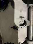
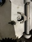
Also, make sure when you reassemble the gear cover that you get the yoke on the governor arm shaft, that rides against the flyball dish, in the correct orientation.

There is a flat side and the rounded/arched side. Though now looking in the -24 parts manual it's a bit confusing to tell exactly how the yoke piece should be pointing away from the "inside surface" of the gear cover...

Either the flats (
#1 Photo) or the round arced side with the bumps (#2 Photo) are pointing up against the flyball cover/dish to operate properly.

#1 Flats towards Governor Cover?

IMG_4064.jpg

#2 Rounded radius arc towards Governor Cover?
IMG_4063.jpg

You might recall how it came apart, though if someone had been in there before & rotated it incorrectly during reassembly it might have been wrong...?

Perhaps someone, @Ray70 @Guyfang ,can confirm the correct orientation.
 
Last edited:

Chainbreaker

Well-known member
1,796
1,992
113
Location
Oregon
The TM says "Smooth side" towards the governor flyball cover. By smooth side I believe they mean the curved side, as that would minimize any friction.
That's the logic, less friction with small bump protrusion facing governor cup that I also believed. However, after reviewing both the -24 parts manual & -34 it caused me to question exact yoke orientation. It doesn't show the yoke's orientation profile with those bumps clearly at all given the drawing as depicted. I could make a case for either side being the "Smooth side". The Yoke side with bumps or without the bumps... By "smooth" do they mean flat or with less friction with opposite side with the bumps?

@Offgrid12 Of note as stated in -34 maintenance manual:

"b. Repair. Replace any flyballs that have flat spots or grooves. Replace CUP if race surface is grooved or rough. The governor cup must be a free spinning fit on camshaft center pin, but should be replaced if excessively loose or wobbly. Check distance the center pin extends from the camshaft gear, this distance must be 25/32 inch to give proper travel distance for the cup (see figure 7-24). If it is less, the engine may race; if more, the cup will not hold the balls properly. If distance is too great, drive or press center pin in. If it is too small, replace pin; it cannot be removed without damaging the surface. If aluminum ball spacer openings are badly worn, replace ball spacer. (Camshaft must be removed for this. )"
 
Last edited:

Guyfang

Moderator
Staff member
Moderator
16,782
24,116
113
Location
Burgkunstadt, Germany
Also, make sure when you reassemble the gear cover that you get the yoke on the governor arm shaft, that rides against the flyball dish, in the correct orientation.

There is a flat side and the rounded/arched side. Though now looking in the -24 parts manual it's a bit confusing to tell exactly how the yoke piece should be pointing away from the "inside surface" of the gear cover...

Either the flats (
#1 Photo) or the round arced side with the bumps (#2 Photo) are pointing up against the flyball cover/dish to operate properly.

#1 Flats towards Governor Cover?

View attachment 913679

#2 Rounded radius arc towards Governor Cover?
View attachment 913680

You might recall how it came apart, though if someone had been in there before & rotated it incorrectly during reassembly it might have been wrong...?

Perhaps someone, @Ray70 @Guyfang ,can confirm the correct orientation.
Its been a LOOOOOOOOOOONG time since I have had this open in my hand. BUT, I THINK, it was the flat/curved side against the cover.
 

Chainbreaker

Well-known member
1,796
1,992
113
Location
Oregon
Its been a LOOOOOOOOOOONG time since I have had this open in my hand. BUT, I THINK, it was the flat/curved side against the cover.
So, in Post #65 photo #2 position is the consensus?

That was my initial inclination making the most sense to me, and apparently Ray also, from a mechanical contact perspective with something that moves in & out (the governor cup).
 

Offgrid12

Member
30
41
18
Location
NY Adirondacks
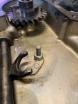
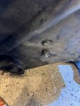
Fixed the governor pin. I drilled right through the cover and tapped for a 1/4" bolt. I used a bolt that was not threaded the whole way. I cut off the head of the bolt, leaving the amount I needed sticking out. About 1/2". The threaded portion was the perfect length for going through the cover and adding a nut on the other side.
You guys are right about the orientation of the forks. The curved side faces the governor cup. (at least it was on mine)
CB, thanks for that info on checking the fly ball setup. I will look at that as well.
Everything about the governor so far seems in real good shape and move smoothly.


IMG_1222.jpegIMG_1221.jpeg
 
Last edited:

Chainbreaker

Well-known member
1,796
1,992
113
Location
Oregon
Now... anxiously awaiting the results of the governor/flyball etc. inspection. Gotta be a problem somewhere that explains the governor erratic overspeed issues your experiencing.

@Offgrid12 Edit: Also, check to make sure that there is a "ball bearing" at the free end of the governor shaft where it mounts into the "needle bearing". if you shine a small flashlight you can see the round surface of the ball bearing reflecting back at you. I recall the -34 maintenance manual mentions to verify the ball bearing hasn't fallen out and to put some grease in there before reinserting that end of governor shaft into needle bearing.
 
Last edited:

Offgrid12

Member
30
41
18
Location
NY Adirondacks
Well, I think I fixed it!

I did an inspection of the fly ball assembly, and everything checked out good. No abnormal wear to the governor cup, or the ball bearings. The fly ball shaft stick out measurement was spot on at 25/32.

When I had the governor cover off I was reading old posts on a different website about someone with over speeding issue on there 002. What they ended up figuring out was that the governor arm (arm that comes out of the gear cover and attached to the throttle link) was bent to far up. So when I had the governor cover on the bench, I bent the arm down a bit. So it would be somewhat more toward horizontal when its on the machine.

Got it all reassembled and started it up. Figured out I had bent it a little to far down as it wouldn't allow enough fuel to get up to speed. I bent the arm up by hand just a tad more and started it back up. I set the speed to 61hz, and it stayed there for over an hour! Governor also reacted perfectly when I moved it with my finger. I'm not exactly sure how far I actually ended up tweaking the arm down. Maybe a 1/2"? Not sure though.
I'm not sure why it went from running well to needing this adjustment, but it seems to be working good!

CB, I just saw your note about that little ball bearing at the end of the gov shaft. I didn't see your post until after putting it together, but I did notice that ball bearing. When I was holding the gov cover, I could hear something rattling. I figured out it was that little ball bearing. It actually seemed to be stuck in there somehow. Maybe the needle bearing had to come out first as it was behind that.
 
Last edited:

Chainbreaker

Well-known member
1,796
1,992
113
Location
Oregon
That's great news! Though, VERY ODD that the Governor Arm somehow got tweaked so far off without any known event to cause it to get bent/tweaked.

However, what Ray70 suggested earlier in Post #5 up above regarding potential "Sticking Governor Linkage" inside the little piston-like cylinder thingy, not the arm itself, might explain that sort of anomaly if it were slightly bent or the spring inside it somehow got tweaked, bent or broken & was stuck in an odd position causing the linkage to be fixed & not respond normally... just a thought.

At least you know the whole "flyball assembly & gear cover mechanism" is all good to go and with the deleted roll pin mod it will never come out & destroy the engine! (y)
 
Last edited:

Chainbreaker

Well-known member
1,796
1,992
113
Location
Oregon
....
CB, I just saw your note about that little ball bearing at the end of the gov shaft. I didn't see your post until after putting it together, but I did notice that ball bearing. When I was holding the gov cover, I could hear something rattling. I figured out it was that little ball bearing. It actually seemed to be stuck in there somehow. Maybe the needle bearing had to come out first as it was behind that.
Yeah, I was wondering if you might miss that post & later went back and flagged it to you in hopes you might see it before reassembly. Regardless, your ball bearing is there so you are good to go!

I too noticed that the ball bearing would not fall out with the needle bearing installed, so I think the note in the -34 maintenance manual might be there due to the ball bearing having occasionally fallen out during OEM assembly or someone doing repairs while replacing that needle bearing ... perhaps that's why the suggestion of greasing it. The grease might have been meant as assembly grease to retain it in place while inserting a needle bearing as its going to get oiled anyway.

Any way... your obviously good to go in your repair instance!
 
Last edited:

Ray70

Well-known member
2,597
5,917
113
Location
West greenwich/RI
Definitely good to hear you have it running good again. As CB said, I have to wonder if bending the arm is compensating for something else being out of whack. Reason I say that is 1) there's little chance that the arm got bent while in use in your possession and 2) one of the specific pictures I asked you to get was so I could see the tip of the governor arm in relation to the top of the fuel stop solenoid, so I could try to see if the arm looked bent, but it appeared to be just about right, tip of the adjustment slot just slightly above the top of the solenoid.
Regardless, good job sticking it out, doing the investigation and getting it running correctly again! Congrats!
Next thing I would do is perform a full load test and assess the governor's ability to hold the Hz within tolerance, because a tweaked governor arm can also cause difficulty maintaining frequency under load, regardless of droop adjustment.
 

Offgrid12

Member
30
41
18
Location
NY Adirondacks
Definitely good to hear you have it running good again. As CB said, I have to wonder if bending the arm is compensating for something else being out of whack. Reason I say that is 1) there's little chance that the arm got bent while in use in your possession and 2) one of the specific pictures I asked you to get was so I could see the tip of the governor arm in relation to the top of the fuel stop solenoid, so I could try to see if the arm looked bent, but it appeared to be just about right, tip of the adjustment slot just slightly above the top of the solenoid.
Regardless, good job sticking it out, doing the investigation and getting it running correctly again! Congrats!
Next thing I would do is perform a full load test and assess the governor's ability to hold the Hz within tolerance, because a tweaked governor arm can also cause difficulty maintaining frequency under load, regardless of droop adjustment.

I too am a little confused why it was working well, and all of a sudden got out of whack. Maybe tomorrow ill compare how the arm looks now, compared to the pic I posted earlier.
I mentioned earlier in this thread that when running, my AC voltage was off... At startup today, I found this was still the case. I read 160v and 320v where I should have read 120v and 240v. Voltage adjust knob did nothing.
Fast forward an hour of running when I went out to check on it, it was showing normal 120v/240v. Also the voltage adjust knob was now working. At this point I put a 1500w heater on and ran it for another 20mins.
Form reading the forum it sounds like if something happens in the voltage adjust circuit, it will just go to full voltage? In this case 160v/320v? It sounds like other 002 or 003 owners have had the voltage go to 160v/320v and a new AC VR did not fix it. Maybe I should start a new post on this issue hahah. I really appreciate everyone's input in this thread.
 

Ray70

Well-known member
2,597
5,917
113
Location
West greenwich/RI
Well, keep a close eye on the voltage output. In my experience when the voltage goes up to 320, that typically means one or more of the 3 transistors on the VR is going bad. In the past I would normally replace all 3 transistors, but now @kloppk offers a sweet replacement VR that drops right in.
The VR is not the only reason for voltage pegging, the CVT-1 can also be a culprit, but if it comes and goes I'd lean towards the VR first.
 
Top
AdBlock Detected

We get it, advertisements are annoying!

Sure, ad-blocking software does a great job at blocking ads, but it also blocks useful features of our website like our supporting vendors. Their ads help keep Steel Soldiers going. Please consider disabling your ad blockers for the site. Thanks!

I've Disabled AdBlock
No Thanks