• Steel Soldiers now has a few new forums, read more about it at: New Munitions Forums!

  • Microsoft MSN, Live, Hotmail, Outlook email users may not be receiving emails. We are working to resolve this issue. Please add support@steelsoldiers.com to your trusted contacts.

Need a wire diagram for a m1078 a1. 2001. Transmission schematic.

Xengineguy

Well-known member
Supporting Vendor
227
775
93
Location
USA Indiana
I tried to download and save from this site however after the download I can only view page 1. When I select
a different page it goes back to page one ?? Thanks for your help. Mike
 

MatthewWBailey

Thanks for this site. My truck runs great now!
Steel Soldiers Supporter
863
1,567
93
Location
Mesa Colorado
I noticed the schematics in the back of the TMs don't remotely match an A1 but the FMTV pdf above does of course. However, there's lots of stuff not on those A1 sheets, like cables in the PDP and other wiring info. Is there a TM document that shows the A1 stuff as it's shown in the A0 docs? For example, what is connector P250?
 

Attachments

GeneralDisorder

Well-known member
Steel Soldiers Supporter
2,076
5,308
113
Location
Portland, OR
I noticed the schematics in the back of the TMs don't remotely match an A1 but the FMTV pdf above does of course. However, there's lots of stuff not on those A1 sheets, like cables in the PDP and other wiring info. Is there a TM document that shows the A1 stuff as it's shown in the A0 docs? For example, what is connector P250?
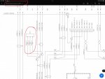
It's on sheet 20 of the A1/A1R schematic in the PDF. P250 is for one of the two the J1939 databus termination resistors.

If you want the simplified diagrams for each subsystem you have to dig into the electronic manuals. And sometimes they make you work for it. They are an acquired skill to find stuff in.

BUS4f01_large.jpg
 

Attachments

Last edited:

MatthewWBailey

Thanks for this site. My truck runs great now!
Steel Soldiers Supporter
863
1,567
93
Location
Mesa Colorado
It's on sheet 20 of the A1/A1R schematic in the PDF. P250 is for one of the two the J1939 databus termination resistors.

If you want the simplified diagrams for each subsystem you have to dig into the electronic manuals. And sometimes they make you work for it. They are an acquired skill to find stuff in.

View attachment 918502
Ok I see it on page 20. I was trying to use the TM PDFs bc they are more detailed. The hydraulic schematics are very useful. But Electricals are clearly different.

By electronic manuals do you mean those 1700 page PDFs 1-5 or another media? I've not made much sense of those PDFs so far after numerous attempts.

66651CDC-DF94-4087-BB6F-39F607C49BA1.png
 

MatthewWBailey

Thanks for this site. My truck runs great now!
Steel Soldiers Supporter
863
1,567
93
Location
Mesa Colorado
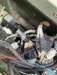
Yep, that grey thing is a data bus termination resistor… R13?

have you looked at this early A1 diagram?
That's the one I've been using, since I discovered quickly that the wires don't match up to the generic TMs. Every time I open the PDP or the driver dash, it's like searching for the lost ark. I've only added a camera system and now the victrons so Ive basically tap off the X terms for that stuff without needing schematics. But, if I had to troubleshoot anything (like my non functioning water temp), I'm just chasing bread crumbs it seems. The government and their revisions.
 

Ronmar

Well-known member
3,881
7,549
113
Location
Port angeles wa
Done. Thank you—
Actually the bottom half of the pages in that document you found has the same info as the A1 diagram already posted in the TM section, but the first half appears to contain the diagrams from the earlier version of the A1 truck, that I started referring to as the A0.5. Basically an A0 with a 3126 engine, green circuit card power panel, but no LBCD or battery disconnects...

I only got a glance at it this morning, but those items missing from the first diagram jumped right out at me. I will look at it a little closer tonight, but great find!
 

hike

—realizing each day
Steel Soldiers Supporter
538
849
93
Location
Texas Hill Country
Actually the bottom half of the pages in that document you found has the same info as the A1 diagram already posted in the TM section, but the first half appears to contain the diagrams from the earlier version of the A1 truck, that I started referring to as the A0.5. Basically an A0 with a 3126 engine, green circuit card power panel, but no LBCD or battery disconnects...

I only got a glance at it this morning, but those items missing from the first diagram jumped right out at me. I will look at it a little closer tonight, but great find!
The previously posted one misses R13 for the later serial numbers; perhaps other particulars?
 
Top
AdBlock Detected

We get it, advertisements are annoying!

Sure, ad-blocking software does a great job at blocking ads, but it also blocks useful features of our website like our supporting vendors. Their ads help keep Steel Soldiers going. Please consider disabling your ad blockers for the site. Thanks!

I've Disabled AdBlock
No Thanks