Yeah i think youre right for it being an air leak source, and also correct on the location, that is from the fuel selector to the first pump.
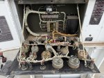
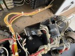
So cleaned out everything, new filters and it will run. Remember that IDLE/RUN toggle on the front i told yall about? Well it will change the rpm from low speed to operating speed so not sure what thats about, its also finnicky and i will have to toggle it up and down sometimes to keep at operating rpm. When running and start switch held and Voltage/Amp knob on L1-L0 i get 120vac on the genset gauge, toggle CKT BRKR switch to CLOSE and i get 120v on each leg measured at the main connection point, HTZ gauge reads 0 though, (OK. The hertz meter is driven by the A2, (Frequency Converter). Open the control panel and test the input side of the A2. You should get 120 VAC, 400 hertz there. If so, the A2 or the M6, (Freq Meter) is bad. If you have a half way decent DMM, it will measure hertz. Just stick it in the 120 volt outlet, (make sure its hooked up and the CB-3 is pushed in. If you get no reading at CB-3, go to the output load terminals and test there. Use the AC volt adjuster to get 120 volts and the hertz adjuster to 400 hertz. You want to make sure the A-23, (electric governor) and A-24, (Electric Actuator) are working.) will that only show a reading when its outputting a load? (No. It works all the time)
When it cools down im going to pull the head off the injection pump and see how it looks since it seems to be hunting up and down (Do you mean the A24 is moving up and down? Or you can hear the hertz/RPM moving up or down. ) a little…might also be because theres no load? (No. This is a Precise Power gen set. If the A-23 and the A-24 are working right, the Hertz should be ROCK steady) Give me some input on that one.
Going to throw some diesel cleaner in the tank, just for piece of mind for the long run. (Look in the tank with a light. You should be able to see to the bottom and it should be clear, not cloudy. Look for water, it will look like quicksilver in the fuel tank. )
Regulator in alternator (you mean the G2, battery charging alternator?) is shot i think, at operating rpm the output is 32vdc and i have the manual voltage adjuster (you mean the pot on the alternator) on it turned all the way down. (Keep in mind, you operate this set at less than rated speed, you risk damaging the A-11, (Static Exciter)
The front side fuel pump was bad, tore it down, cleaned it and tried to test it straight from the battery and nothing, (I would soak it 1-2 days in a fluid that eats diesel lacquer) even tried beating the shit out of it and no joy, rear pump works great though and is currently installed all by itself. (normal fix. good job) Yall know the approximate working fuel pressure this should be at? Probably going to a COTS option entirely.
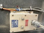
Now on to the 28vdc box. The tag says Input is 3-phase, 200v, 400htz so i switched the genset to L3-L1 which gives me 200vac on the gauge but no reading on the hobart box for DC input.


