• Steel Soldiers now has a few new forums, read more about it at: New Munitions Forums!

  • Microsoft MSN, Live, Hotmail, Outlook email users may not be receiving emails. We are working to resolve this issue. Please add support@steelsoldiers.com to your trusted contacts.

12V Switch Box Relay Electrical Issue

dbeasty

Member
49
12
8
Location
Eastsound, wa
I have developed a strange electrical issue on my 1078 A1.

The vehicle was running like a charm, than I turned off the power disconnect next to battery. After a while turned it back on..

The LEDs were acting funny.. but the truck started,, once it started , all was good.

Than got home, turned off the engine, turned on the the interior light and it went from bright to very dim to none fairly quickly.

Troubleshooting:
1. Charged , cleaned battery connectors, and tested batteries , they are all good.
2. Went to can and started to measure in the fuse box, the 12V battery is just showing 4V.. the 24V battery is showing 24V...
3. Unhooked the 12V battery cable that connects to the back of the fuse box, just to make sure and still measured 4V...
4. I started to disconnect the relays and fuses, but canceled that effort since it made me think the problem is somewhere between the batteries ( which read over 12V ) and the fuse box..
5. Open the switch box , on left there was 24V going through all the way on the right there was going 12V past the switch into a what I think is a relay and only 5V out

So I think the issue the relay or things which feed it ( 12V to 5V makes me think its a relay)..,, so cleaning the contacts and all that good stuff meanwhile.

There are two wires going to the relay from the left and one from the right, any ideas what those are for..?

If cleaning does not work shall I take the relay out and test it somehow?? In short term can I just bypass it??

Is there a thread that covers this issue , so I can read up, or any suggestions. I will update as I go on..
 
Last edited:

NDT

Well-known member
Steel Soldiers Supporter
10,441
6,494
113
Location
Camp Wood/LC, TX
Sounds like LBCD problem. What is LBCD? Load Battery Control Device located near spare tire. It has diodes to protect the alternator in case there is a reverse polarity problem. The cables that attach to it are known to get corroded at the ring terminals.
 

dbeasty

Member
49
12
8
Location
Eastsound, wa
Attaching new image, its some kind of relay.
20200919_200441.jpg
Can I bypass it??

Any idea where to get one , or what is the part number, I suppose can take it out all the way..and see what is on the device..
 
Last edited:

NDT

Well-known member
Steel Soldiers Supporter
10,441
6,494
113
Location
Camp Wood/LC, TX
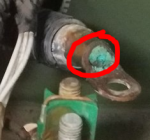
Is that solenoid working good? Looks like it was full of water. The terminal on the cable could have corrosion between the wire strands and the terminal. Will cause your issue also.
 

dbeasty

Member
49
12
8
Location
Eastsound, wa
I did clean up the terminals on the outside off the relay and connector wires, is that what you mean?

Is there a way to disassemble this relay and fix it?

I did find one for $350 on eBay... crazy, so alternatives would be good.
 

fuzzytoaster

Well-known member
Steel Soldiers Supporter
4,299
3,130
113
Location
Fort Worth, Texas
Yes you can bypass those solenoids and yes they've caused that exact same issue on 2 trucks I've had. I sourced a replacement new style unit for $400 out of a company in the North East (I'd have to dig it up) but the other I simply bypassed. Your troubleshooting steps are correct but just to cover everything I propose you..
  1. Check all battery voltage
  2. Trace voltage through system and find where it drops off
  3. Bypass those solenoid
  4. Recheck symptoms
  5. Report back to us
 

Guyfang

Moderator
Staff member
Moderator
16,707
23,945
113
Location
Burgkunstadt, Germany
Can you take better pictures of the data printed on the relay. I found the German manufacturer, and lots of their stuff is in Epay, here in Germany. prices not all that bad.
 

ckouba

Well-known member
Steel Soldiers Supporter
609
1,724
93
Location
Oregon
You may want to re-terminate the cable(s) as well. The ends are looking seriously corroded:

1600625796464.png

Might be just as bad for a short distance under the insulation?
 

dbeasty

Member
49
12
8
Location
Eastsound, wa
I have bypassed the 12V selenoid/relay with the a wire and it worked ok in terms of getting correct reading in the cab etc..
( so definitely the issue is the relay or what is controlling the relay in the battery switch box)

I was looking at this a bit longer and there are four white wires that come in into a switch box on the left and both 24V and 12V relates controlled by the same inputs as far as I can tell.

How is this supposed to work ?
Would be good to know how to test that relay so I can make sure its the relay not what its controlling it..and understand that system.

If you get positive voltage on the relay ends control ends does it disconnects, so there is n incorrect polarity??

I will also need to cleanup the 24 volt relay side, the corrosion on big wires was just superficial but it does not hurt to have it cleaner.
 

mechanicjim

Member
90
40
18
Location
Chicago il
1600696687505.jpeg

could it be this part the Dual battery Control relay?

this is a picture from the Aug 2019 PS MAG it has the NSN for that of 5945-01-501-8715 maybe that will help source parts?
 

dbeasty

Member
49
12
8
Location
Eastsound, wa
The relays in question are the 30.313.12.901
I want to make sure they are really the source of this issue.. and defective.

Almost considering dump this complexity and just have a proper bypass, which is not easy to do since the wires are huge.. what gage should I be using? or well maybe just a metal bar would be even a better idea..

I did little reading and I think if there is no voltage across the control ends of the relay.., its should be closed ,.. so will test that.

Either the relays/selenoid are bad, or there is something else that is triggering, so yes cleaning up around on the 24V side needs to be done and also got the message that redoing the corroded ends might be a good idea, just have to take it somewhere to have it done, since do not have such a large connectors...
 

Guyfang

Moderator
Staff member
Moderator
16,707
23,945
113
Location
Burgkunstadt, Germany
The relays in question are the 30.313.12.901
I want to make sure they are really the source of this issue.. and defective.

Almost considering dump this complexity and just have a proper bypass, which is not easy to do since the wires are huge.. what gage should I be using? or well maybe just a metal bar would be even a better idea..

I did little reading and I think if there is no voltage across the control ends of the relay.., its should be closed ,.. so will test that.

If you have no voltage across the X1 and X2 control terminals, then the relay should be open.


Either the relays/selenoid are bad, or there is something else that is triggering, so yes cleaning up around on the 24V side needs to be done and also got the message that redoing the corroded ends might be a good idea, just have to take it somewhere to have it done, since do not have such a large connectors...
 

dbeasty

Member
49
12
8
Location
Eastsound, wa
Let me get this right, since its important for me to know how it supposed to work.
1. closed / aka closed circuit , the current is flowing,
2. open circuit = current is not flowing.

Are you saying if there is NO Voltage on X1 and X2 control terminals than the circuit is open hence nothing is conducting..

In order to get power to the truck I need at some point on X1, and X2 voltage power so the main circuit is closed and have power to the rest of the truck.

For some reason I thought it was just opposite..., which if there is no voltage on X1, or X2 the current flows to the truck.

( sorry this is important for me to find out as to what is wrong..) since I am not getting any voltage on X1 or X2 ..
 

Guyfang

Moderator
Staff member
Moderator
16,707
23,945
113
Location
Burgkunstadt, Germany
Let me get this right, since its important for me to know how it supposed to work.
1. closed / aka closed circuit , the current is flowing,
2. open circuit = current is not flowing.
Correct.

Are you saying if there is NO Voltage on X1 and X2 control terminals than the circuit is open hence nothing is conducting..
Correct. Normally. Most relays are open when not there is no 24 VDC applied to X1 and X2. There are some relays that reverse several different contacts when voltage is applied, but I do not think your relay is so. Its to turn on, and turn off voltage. And that is normally done by applying or removing voltage to the control circuit, X1 and X2. X1 normally being the hot wire, X2 normally being the path to ground.

In order to get power to the truck I need at some point on X1, and X2 voltage power so the main circuit is closed and have power to the rest of the truck.
Correct.

For some reason I thought it was just opposite..., which if there is no voltage on X1, or X2 the current flows to the truck.
The reason for this is, when you shut off main power, nothing should be powered up. Think of it this way, if you turn off a system, any system, lets say because it starts to burn up, and off TURNS ON a relay, how can you stop farther damage?

( sorry this is important for me to find out as to what is wrong..) since I am not getting any voltage on X1 or X2 .
Try this. Go from X2 to a ground point. A good ground point. You should measure ohms from ground to X2 and it should read continuity. If you turn on the truck, you should get 24 VDC when the relay SHOULD be powered up. If that voltage is not there, something is not working farther upstream. To test the relay, you can simply apply 24 VDC to X1, and it should close. I have no idea what this relay powers up. I am a generator guy. So I would remove the relay to test it. 24 VDC to X1 and X2, the relay should close, (you might even hear a clunk) and measure between the two output terminals for continuity.
 

dbeasty

Member
49
12
8
Location
Eastsound, wa
Yes that makes sense.
Ordered the updated version of this entire 3106
Link to relay

Which looks totally different from mine.. but that is good thing.

There are two positives coming into the 3106 per other PDF I posted, one is voltage regulator and the other one is some kind of cutoff, not sure how the one works.
So for batteries being connected I need both positive.
I can only speculate that there must be some direct battery connect or something like that , since I do not know how these would get positive voltage if the relays are open.
 

Guyfang

Moderator
Staff member
Moderator
16,707
23,945
113
Location
Burgkunstadt, Germany
Something else I forgot to write.

1600893295037.png
A schematic, will always show you the circuits, POWERED DOWN. Always.

This is a generic diagram. A relay very much like yours. This one is called K2.
Terminal X1 SHOULD be hot.
Terminal X2 SHOULD be ground.
BUT, if you would change them up, the relay would still work. A relay doesn't care how you hook it up. 24 VDC, is 24 VDC.

Terminal A1 SHOULD be hot.
Terminal A2 SHOULD go to what ever you want to power up. A motor, a radio, a system. Normally its called a LOAD.
BUT, if you would change them up, the relay would still work. A relay doesn't care how you hook it up. 24 VDC, is 24 VDC. So long the Hot is separated from the Load until you turn on the relay.

The round part is the coil.
The "Hat", or T above A1 and A2 is the bridge that makes the connection when VDC is applied to X1 and X2. Notice its "Open". Because its not powered up.

1600893927862.png
This is another way to show the K2, and the load it powers up, the L4 starter.

1600895006804.png
This is the third way. K3 coil is shown down below. K3 contacts are shown up above. So when looking for what be powering up your relay, you need to know what type of schematics you have.
 
Last edited:

dbeasty

Member
49
12
8
Location
Eastsound, wa
Thanks for explaining the schematics for the relays.
It would be good to get an electrical schematic for the A1.

Replaced the entire 3106 circuit ( automatic battery disconnect) yesterday with the update version and the LMTV is now fully functioning.
 
Top