- 7,058
- 147
- 63
- Location
- Mid Hudson Valley NY
All,
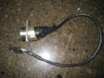
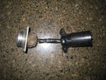
This is some helpful info on building a trailer wiring "connector bender" for towing a MIL trailer equipped with the standard military harness/plug with a civilian type vehicle equiped with a 4,6, or 7 wire towing harness. This "connector bender" allows you to keep the stock wiring in your tow vehicle and trailer, and not alter either. Be mindful of 12/24V voltage issues. The Trucklite Omnivolt lights are a good way around this problem. Truck-Lite - Catalog Product : Rear LED Composite Lamps They are for sale on Ebay from time to time.
This same info can be used to make a "mil tow vehicle to civy trailer" connector bender also, just change the ends.
Obviously, using a civilian tow vehicle will not have blackout lights, nor will a civlian trailer towed by a MIL truck, and they are not discussed here, nor is parts suppliers.
Here is the info you need to know.
Civilian trailer wiring
Green wire = Right turn/stop light
Yellow wire = Left turn/stop light
Brown wire = Tail/marker/running lights
White wire = Ground
Military harness circut # and Pin
22-460 Pin J = Right turn/stop light
22-461 Pin B = Left turn/stop light
21 Pin E = Tail/marker lights
90 Pin D = Ground
Important note: Do not use circut 37/Pin K for a ground. Many times it is terminated and not connected to the trailer chassis. Circut 90/Pin D is ALWAYS the mil trailer ground.
Additional info on the civilian end of it can be found here:
Trailer Wiring Diagram For 4 Way, 5 Way, 6 Way and 7 Way circuits
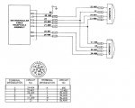
A "diagram" of sorts of how it looks schematically is as follows:
Function Civilian 4 wire - MHC# Pin Letter in plug
Right turn/stop light Green wire - 22-460 Pin J
Left turn/stop light Yellow wire - 22-461 Pin B
Tail/markerlights Brown wire - 21 Pin E
Ground White wire - 90 Pin D
MHC# = Military Harness Circut # (small metal wire bands ID'ing wire)
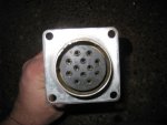
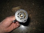
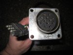
The electrical receptical in the picture is an MS75021-2
One of the many manufacturers for this is BMI #870126B
They are frequently found on ebay, at MV parts houses, and on the back of every US Military MV that has an M series #. I like to buy cheap used/old MV harnesses on ebay, and MV shows as they are always good for sources of wire, connectors, cannon plugs, pins, and these recepticals.
One note on the receptical. There are 2 "ridges" on the receptical that keep the trailer's plug in tight. Sometimes you may need to sand them down a bit with a wire wheel so it is easier to get the plug on and off, but dont do it too much or else the plug will fall out. A little at a time is the way to go.
UPDATED INFO:
If you have a military pigtail coming off your trailer, here are the color codes that correspond to the wire circut numbers. The wire colors are the indiviual wires that are INSIDE the outer black rubber insulation.
24-484
22-461 LEFT TURN/BRAKE RED WITH WHITE TRACER
24-483
21 MARKER LIGHTS RED
23
90 GROUND BLACK WITH RED AND WHITE TRACERS
22-460 RIGHT TURN/BRAKE BLACK WITH RED TRACER
37
Attachments
-
38.8 KB Views: 1,978
-
76.9 KB Views: 1,087
-
62.9 KB Views: 922
-
81.1 KB Views: 825
-
79.3 KB Views: 769
-
85.2 KB Views: 800
Last edited:


