• Steel Soldiers now has a few new forums, read more about it at: New Munitions Forums!

  • Microsoft MSN, Live, Hotmail, Outlook email users may not be receiving emails. We are working to resolve this issue. Please add support@steelsoldiers.com to your trusted contacts.

Custom winch wiring.

ramdough

Well-known member
1,554
1,729
113
Location
Austin, Texas
I have an A0 winch with the harness from that.

I am installing on an A1 truck. Instead of wiring into my truck harnesses, I am proposing rewiring it to be always hot. I took a crack at the wiring schematic.

Will post next post the pictures.

@Ronmar any thoughts? Anyone else?


Sent from my iPhone using Tapatalk
 

ramdough

Well-known member
1,554
1,729
113
Location
Austin, Texas
So, as you can see here, I have eliminated all connections back to the transmission and engine while bypassing the transmission checks.

346B2C40-A2DD-42D5-99F0-36CFFA6AC95A.jpeg

you can see blue as my comments.

the one thing I do not know what to do yet is the PTO light. That mentions a pressure sensor. I am guessing that is an on/off pressure switch with 12v on it. Can anyone confirm thevoltage in the indicator panel?
77415589-5A1C-4A73-83B7-F46603423468.jpeg

any suggestions?
 

Guruman

Not so new member
Steel Soldiers Supporter
here's the A0 setup. simplified a bit.

You can ignore the 1811 wire as it's for the dump truck.

Apply power to 2019 to engage the PTO.

2021 returns a signal from the pressure switch (to let the truck know the PTO is "on", maybe?)

2005 and 2008 are for winch in/out.


3 wires to make it work at a minimum.

The only other thing that happens is that from the switch side, a wire runs into the transmission controller to let it know it's been enabled.


Screen Shot 2022-08-21 at 9.51.46 AM.png
 

ramdough

Well-known member
1,554
1,729
113
Location
Austin, Texas
here's the A0 setup. simplified a bit.

You can ignore the 1811 wire as it's for the dump truck.

Apply power to 2019 to engage the PTO.

2021 returns a signal from the pressure switch (to let the truck know the PTO is "on", maybe?)

2005 and 2008 are for winch in/out.


3 wires to make it work at a minimum.

The only other thing that happens is that from the switch side, a wire runs into the transmission controller to let it know it's been enabled.


View attachment 881036
That is basically what I am planning, but my schematic includes the power source and the PTO relay.

I do want the PTO dash light to work, so I need to find the voltage and a good place to tap into that.


Sent from my iPhone using Tapatalk
 

Ronmar

Well-known member
3,825
7,427
113
Location
Port angeles wa
I think the main reason for the transmission controller interface/approval was to limit overall load/HP thruput in the transmission, as they use allison trans pto output to do a lot of things, and it can deliver a significant amount of HP. I dont think the use of a winch will ever add enough load to really cause any issues, so I dont see outside winch control as an issue.

You don’t need a voltage to drive the dash light in the instrument panel, that is already provided, you simply need to provide a path to ground to activate it Like that pressure sw does.

If I am understanding how these operate correctly, that pressure switch is on the PTO drive gearbox assembly. It is measuring the pressure applied from the transmission to engage the clutch pack in the PTO drive that engages the pump. So light on should = pto clutch pressure available and pressurized/engaged in the normal system. This sounds like it would be a good thing to keep.

So I guess my first question would be does your A1 have P913 pin 13? That is the pin that gets grounded to light the light. That A1 drawing shows the same wire numbers and connectors and pins as the A0 drawing Gruman posted, so if you plug in P/J 913 in the cab and the P210 and 216 connections down to the PTO gearbox solenoid and pressure sw are made, the dash light may work just fine when the PTO solenoid is powered.

You can test this by jumping P216 pin A to B at the PTO gearbox…
 

Mullaney

Well-known member
Steel Soldiers Supporter
Supporting Vendor
7,711
19,751
113
Location
Charlotte NC
I have an A0 winch with the harness from that.

I am installing on an A1 truck. Instead of wiring into my truck harnesses, I am proposing rewiring it to be always hot. I took a crack at the wiring schematic.

Will post next post the pictures.

@Ronmar any thoughts? Anyone else?


Sent from my iPhone using Tapatalk
.
I would like to offer that the PTO switch - meaning PTO On and PTO Off needs to be in your circuit.

I don't think that you want the PTO and by extension the Hydraulic Pump to be on all the time. Maybe I am misunderstanding your goal, but PTO Off could be really important if you were to spring a leak in the system. I also don't think that you would want the pump to run for hours while you drive three or four hours over the bridge and through the woods grandma's house ;-) . The factory hydraulic tank isn't very big and fluid has to circulate if the pump is spinning. That spinning generates heat. Like most other things on these trucks, heat kills.
 

Ronmar

Well-known member
3,825
7,427
113
Location
Port angeles wa
.
I would like to offer that the PTO switch - meaning PTO On and PTO Off needs to be in your circuit.

I don't think that you want the PTO and by extension the Hydraulic Pump to be on all the time. Maybe I am misunderstanding your goal, but PTO Off could be really important if you were to spring a leak in the system. I also don't think that you would want the pump to run for hours while you drive three or four hours over the bridge and through the woods grandma's house ;-) . The factory hydraulic tank isn't very big and fluid has to circulate if the pump is spinning. That spinning generates heat. Like most other things on these trucks, heat kills.
The pto on/off sw is still in there, it is S5/6 in his first A1 drawing above CB45 which provides the winch power. he is just going to send power from that on/off sw right to the pto relay, instead of sending it to the trans, which then powers the pto relay.
 

ramdough

Well-known member
1,554
1,729
113
Location
Austin, Texas
The pto on/off sw is still in there, it is S5/6 in his first A1 drawing above CB45 which provides the winch power. he is just going to send power from that on/off sw right to the pto relay, instead of sending it to the trans, which then powers the pto relay.
Exactly the plan.


Sent from my iPhone using Tapatalk
 

Wingnut13

Well-known member
235
562
93
Location
Strafford, NH
As I recall from reading about the PTO/Allison setup…. The trans has to remain in neutral because the torque converter is locked up when the PTO is engaged. I would guess you wouldn’t want extensive use heating the trans fluid from an unlocked converter transferring power. Also I recall max PTO power was like 75HP, which it a ton…. Wish I could recall where I read all of that.
 

Guruman

Not so new member
Steel Soldiers Supporter
As I recall from reading about the PTO/Allison setup…. The trans has to remain in neutral because the torque converter is locked up when the PTO is engaged. I would guess you wouldn’t want extensive use heating the trans fluid from an unlocked converter transferring power. Also I recall max PTO power was like 75HP, which it a ton…. Wish I could recall where I read all of that.
On the A0 at least the trans does not have to be in neutral.


If you're in neutral and you engage the PTO it will keep you in neutral. But if you are already in gear, it will not shift you into neutral, you can winch and drive at the same time, either forward or reverse.
 

Ronmar

Well-known member
3,825
7,427
113
Location
Port angeles wa
As I recall from reading about the PTO/Allison setup…. The trans has to remain in neutral because the torque converter is locked up when the PTO is engaged. I would guess you wouldn’t want extensive use heating the trans fluid from an unlocked converter transferring power. Also I recall max PTO power was like 75HP, which it a ton…. Wish I could recall where I read all of that.
Yea but it doesnt have to remain in neutral, there is a way around the neutral requirement in the standard installations if I recall correctly.

Since you are not commanding the trans for PTO control, you are correct, it won't ever go into lockup, but a little added throttle will cause the TC to deliver plenty of power for the winch without all that much heat generated. Oops, i had this all wrong as applies to the PTO… Torque converter lockup has no effect whatsoever on the PTO drive gear. Its hard coupled to the turbine housing/engine flywheel…
 
Last edited:

ramdough

Well-known member
1,554
1,729
113
Location
Austin, Texas
Understood, just thought I’d bring that point up. I’m not for or against factory wiring. Or neutral/in gear winching. I’d personally like the option. I’m also about ready to wire my winch up. All the hard mechanical stuff is done. I just need some “spare time”….
Maybe wire in a lock up switch? Not sure what that would entail.

I think I will still just wire as I describe above. I would like to use drive tires when winching.


I forgot the discussion, but I am assuming Mode in manual 1st or second would be the proper option. Thoughts?


Sent from my iPhone using Tapatalk
 
Last edited:

Ronmar

Well-known member
3,825
7,427
113
Location
Port angeles wa
As I recall from reading about the PTO/Allison setup…. The trans has to remain in neutral because the torque converter is locked up when the PTO is engaged. I would guess you wouldn’t want extensive use heating the trans fluid from an unlocked converter transferring power. Also I recall max PTO power was like 75HP, which it a ton…. Wish I could recall where I read all of that.
You know the mind is a funny thing. That little exchange earlier dredged up a memory and a previous discussion I had completely forgot. The PTO drive gear is on the back end of the turbine housing, which is hard bolted to the flywheel. The rear half of that housing is the TC pump, the TC stator is the driven part of the TC that sets forward of the pump and outputs thru a shaft out the middle of the turbine housing to the gearbox. The lockup clutch is on the front of that stator assembly and couples the stator to the flywheel/turbine housing as commanded when RPM between turbine and stator are in coincidence 3rd gear and above. That lockup only applies to the drive output into the main gear box. The accessory drive gear always turns at engine RPM. It drives the scavenger pump via a fixed PTO on the passenger side and the winch PTO when its clutch is pressurized…
 

Ronmar

Well-known member
3,825
7,427
113
Location
Port angeles wa
Maybe wire in a lock up switch? Not sure what that would entail.

I think I will still just wire as I describe above. I would like to use drive tires when winching.


I forgot the discussion, but I am assuming Mode in manual 1st or second would be the proper option. Thoughts?


Sent from my iPhone using Tapatalk
I think the only thing I would caution against is engaging the PTO at high RPM, and of course with the winch in or out switch engaged To make things as easy on the PTO clutch pack as possible. The winch PTO drive gear is hard coupled to the transmission so, like the scavenger pump on the opposite PTO port, is always turning and will accept any engine RPM given it. The hydraulic pump probably wont care what RPM it is run at once engaged either. But it takes a little bit to move fluid, and it will have some added resistance when cold, so I would not engage it above idle. Once engaged the power required from the PTO is directly proportional to the winch load placed upon it.
 
Last edited:

ramdough

Well-known member
1,554
1,729
113
Location
Austin, Texas
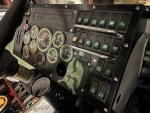
Found these accessory connectors under my new dash:


I am contemplating how much I want to tie my old harness to my new wiring.


Sent from my iPhone using Tapatalk
 
Top