RRaulston
Well-known member
- 227
- 552
- 93
- Location
- Sahuarita, Arizona
So..... where can you get a CTIS pressure switch for less than $500??? ouch....
Steel Soldiers now has a few new forums, read more about it at: New Munitions Forums!


if your speaking of the one on the tank.... yeah those are OUCHHHSo..... where can you get a CTIS pressure switch for less than $500??? ouch....
| CTIS Pressure Switch on air tank | TruckPro/Spicer | 599959 |
Thats a tough one. Like the alternators, It is a pretty specific component, and the bandits know it. Thats why I like to throw out cost effective alternatives whenever I canSo..... where can you get a CTIS pressure switch for less than $500??? ouch....
") The CTIS sw closes at 117 and doesn’t open again until 89PSI. But there are inexpensive off the shelf 90-120 PSI air compressor switches. I have not found one with normally open contacts though, so these open at 120 and close at 90 to cycle an air compressor this is opposite of the CTIS sw. You could invert that output with a relay, so maybe $20 in parts and a little bit of wiring?
The CTIS sw closes at 117 and doesn’t open again until 89PSI. But there are inexpensive off the shelf 90-120 PSI air compressor switches. I have not found one with normally open contacts though, so these open at 120 and close at 90 to cycle an air compressor this is opposite of the CTIS sw. You could invert that output with a relay, so maybe $20 in parts and a little bit of wiring?I agree. It would not be hard to do this with a weather-proof box. Speaking of inexpensive work-arounds, like the penny collection I started in the old farm house fuse box. Who needs fuses, when a penny will suffice? Old Abe trickThats a tough one. Like the alternators, It is a pretty specific component, and the bandits know it. Thats why I like to throw out cost effective alternatives whenever I can
IMO the main purpose of that switch is to allow the air system to recharge fully occasionally. It may be that CTIS also expects to see it open after a certain amount of fill(guessing here)… This behavior could probably be mimicked close enough to keep CTIS happy with a simple programmable interval timer… About $10?

Wouldn't even need a weatherproof box. Cut the connector at the tank and Install the 90-120PSI air compressor sw at the normal location at the tank and install new connections on the end of the wiring harness and weatherproof them to the switch. Splice the relay into the CTIS wiring harness under the trailer and park brake valves in the dash.I agree. It would not be hard to do this with a weather-proof box. Speaking of inexpensive work-arounds, like the penny collection I started in the old farm house fuse box. Who needs fuses, when a penny will suffice? Old Abe trick
Any time that pressure switch is open, the CTIS system will not do anything that consumes air. So for example if you start up with empty tanks, the CTIS system will not even pressurize the wheel valves to check the tire pressure until that switch closes. If it is in an inflate cycle, it will pause the instant that switch goes open. That switch state is continuously monitored. Its been a little bit since I have played with it, but I believe it will continue an already started deflate cycle if the switch goes open during, but as soon as it tries to do a periodic check in of the pressure, it will go back to waiting again until the switch closes, at which point it checks and resumes deflating. Of course for that same reason it will not start new deflate cycle, because it doesn't want to use air for the check.I am not sure exactly how the controller interprets/uses that switch info as I have only ever played with working units briefly.
I suspected as much, and that makes perfect sense, but have no observation to support itAny time that pressure switch is open, the CTIS system will not do anything that consumes air. So for example if you start up with empty tanks, the CTIS system will not even pressurize the wheel valves to check the tire pressure until that switch closes. If it is in an inflate cycle, it will pause the instant that switch goes open. That switch state is continuously monitored. Its been a little bit since I have played with it, but I believe it will continue an already started deflate cycle if the switch goes open during, but as soon as it tries to do a periodic check in of the pressure, it will go back to waiting again until the switch closes, at which point it checks and resumes deflating. Of course for that same reason it will not start new deflate cycle, because it doesn't want to use air for the check.
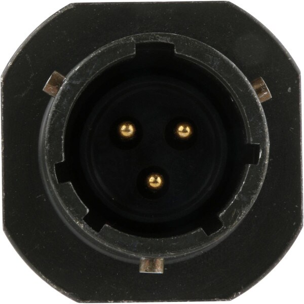
So each button is wired into the big cannon plug giving you manual control of the 3 valves? I'm guessing all 3 buttons have a common 24v power wire going to them and each button then has a different valve wire. Hit the button and send power to the respective solenoid?The pressure control unit is the manifold that the controller manipulates to control the system. It is located under the passenger dash, an aluminum block with hoses connected to it and a black plastic cover on the bottom. It has 3 solenoid valves under that plastic cover. One is the control solenoid, it is normally open to vent the manifold and the controller must energize it to close it and seal the system. It vents the manifold into that plastic cover which has a hose that connects it to a port on the floor to vent the air outside the cab.
The second valve is the supply valve. When the controller energizes it, it lets in supply air from the wet tank to pressurize the system/inflate the tires.
The third valve is the deflate valve. When energized it connects the manifold to a little 6.5PSI pressure relief valve on the side of the manifold block. This vents the system down to that point, which is just enough to keep the wheel valves open. Since the pressure in the tires is greater, air trys to flow back from the tires to the manifold. This reversal in flow causes the dump valves(remote pressure regulators) to vent the tire air rapidly.
The stable pressure it is looking for is the combined tire and system pressure. When the system is sealed and the wheel valves are open the tires should all equalize at the same pressure. If one or two tires are at a different pressure this can take a while to equalize thru the plumbing and the controller may fault Because the pressure is changing.
The only place to really sample the manifold pressure, already has the pressure transducer installed there. You can monitor the pressure at the tire Schrader valves... if you can get it to fill then it was probably faulting because not all the tire pressures were the same initially and it takes a while to equalize them. If low, 30 minutes to fill at idle sounds about right, they take a huge ammount of air. When low, the tires will empty a 120 PSI wet tank down to its 85psi cutoff in 3 seconds...
Finding leaks is a problem on the system as it only pressurizes in pulses and the engine is running. The easiest way is to disconnect the controller connector and jumper 28v to the control solenoid and momentarily jumper 28v to the supply solenoid to pressurize the system(as long as the wet tank is full). the system should then set at tire pressure as long as the control solenoid remains energized and you can look for leaks without the engine running...
my controller was bricked when I got my truck and I decided to go to manual control. Here is a video of how the PCU operates with me controlling the solenoids manually. The gauge on mine is connected where the pressure transducer was connected on the PCU...
That would be correct. You close the control then open the supply or deflate solenoids appropriately to control tire pressure.So each button is wired into the big cannon plug giving you manual control of the 3 valves? I'm guessing all 3 buttons have a common 24v power wire going to them and each button then has a different valve wire. Hit the button and send power to the respective solenoid?
OK I watched this one too. I thought I had watched all your videos but missed this one. This is a cleaner setup.....Awaiting schematics!!That would be correct. You close the control then open the supply or deflate solenoids appropriately to control tire pressure.
That was my prototype. I put up a slide show of that original wiring(drawing and pics) In another youtube video On my channel.
I do it a little differently with a latching relay Now. I am working on a updated drawing that I will publish when I get to it
Here is my current system built into the dash…
