Crapgame
Well-known member
- 642
- 342
- 63
- Location
- Navarre, FL
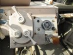
Can somebody please give me the dimensions for the exterior face plate for the FAV Engine Protection System? I am trying to have the face plates made again, at a minimum; the entire functional EPS circuit board if possible. I am talking to a couple different electronics people about the tech possibilities even if a contemporary relay, more efficient and better materials are used.
(If you happen to try to measure with a carpenter tape, can you please lay the edge with measurement increments flat against the area to be measured. The curvature of the carpenter tape is enough to give a false reading, causing a 1/8" to 3/16" difference in the actual dimensions. I ran into this issue when recreating the Special Forces Ground Mobility Vehicle GMV HMMWV dashboard plates for the IR Lights and Air Compressor.)
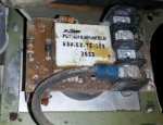
And if possible, can I get a photo of what is between the brown phenolic circuit board itself and silver aluminum faceplate to evaluate the alarm buzzer installation, etc?

Second, Does anybody know how the EPS originally functioned? Example, did the top right amber lamp illuminate when the vehicle was powered to show the board functional? Or did that amber lamp illuminate when the engine temp maxed out to give the crew a visual as well as audible alert the EPS was activated to shut down the engine.
The lower left amber lamp is labelled for "Overheated" would that mean it lights up when the engine reaches the max temp specified to initiate the shutdown or, did it illuminate at a specificed temperature that was rated as overheated, but a few degrees lower than was required by the circuit to shut it down?
The "Emergency Ignition" button on the lower right, I assume to be a momentary push button switch that allows the crew to override the shutdown during combat or life threatening emergency situation where the engine is secondary to human life?
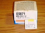
We know the main relay is a Potter-Brumfied R50-E2-Y2-12V , these still turn up for sale but a more contemporary version might be better? Ideally I'd try to stick to an exact copy, if possible, improved relay, acceptable.


I found a pre-made relay circuit board on ebay that is activated by a loss in battery voltage, so the system shuts down when the battery becomes partially drained to prevent you from not being able to start the engine. I bought this to use as a road map to recreating the EPS board, the identification stripes on the EPS capacitors may not be discernable enough to properly ID the components.
(If you happen to try to measure with a carpenter tape, can you please lay the edge with measurement increments flat against the area to be measured. The curvature of the carpenter tape is enough to give a false reading, causing a 1/8" to 3/16" difference in the actual dimensions. I ran into this issue when recreating the Special Forces Ground Mobility Vehicle GMV HMMWV dashboard plates for the IR Lights and Air Compressor.)
And if possible, can I get a photo of what is between the brown phenolic circuit board itself and silver aluminum faceplate to evaluate the alarm buzzer installation, etc?

Second, Does anybody know how the EPS originally functioned? Example, did the top right amber lamp illuminate when the vehicle was powered to show the board functional? Or did that amber lamp illuminate when the engine temp maxed out to give the crew a visual as well as audible alert the EPS was activated to shut down the engine.
The lower left amber lamp is labelled for "Overheated" would that mean it lights up when the engine reaches the max temp specified to initiate the shutdown or, did it illuminate at a specificed temperature that was rated as overheated, but a few degrees lower than was required by the circuit to shut it down?
The "Emergency Ignition" button on the lower right, I assume to be a momentary push button switch that allows the crew to override the shutdown during combat or life threatening emergency situation where the engine is secondary to human life?
We know the main relay is a Potter-Brumfied R50-E2-Y2-12V , these still turn up for sale but a more contemporary version might be better? Ideally I'd try to stick to an exact copy, if possible, improved relay, acceptable.


I found a pre-made relay circuit board on ebay that is activated by a loss in battery voltage, so the system shuts down when the battery becomes partially drained to prevent you from not being able to start the engine. I bought this to use as a road map to recreating the EPS board, the identification stripes on the EPS capacitors may not be discernable enough to properly ID the components.

