• Steel Soldiers now has a few new forums, read more about it at: New Munitions Forums!

  • Microsoft MSN, Live, Hotmail, Outlook email users may not be receiving emails. We are working to resolve this issue. Please add support@steelsoldiers.com to your trusted contacts.

How To - Manual Glow Plug Switch

Warthog

Moderator
Super Moderator
Steel Soldiers Supporter
13,774
232
63
Location
OKC, OK
The stock system works this way:

The stock GP relay is internally grounded. It does not use the mounting bracket for its ground. It needs a power source and a ground source. If you use an external ground relay (ie ford relay), you glow plugs will be on all the time and will burn out quickly.

At the Glow plug relay on the firewall

1 - the small pink wire is hot with 12v whenever the key is on
2 - the small blue wire is the ground for the internal coil and the glow plug relay controls it. When the controller senses the need for the glow plugs it closes the ground circuit and the relay energizes


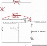
To add a manual switch all you need to do is close the ground circuit. The easiest way is to add a wire to the light blue wire at the relay, a push button switch and a wire to ground. Very simple

Since the relay is handling all the power, the switch is just controlling the internal coil and does need to be rated very high. A 5-10amp switch is more that adequate.
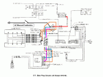
E-07 glowplugs manual switch.GIF
 
Last edited:

tim292stro

Well-known member
2,118
41
48
Location
S.F. Bay Area/California
I was asked about how-to on this today via PM, I agree with Warthog on its usefulness and his implementation, and will offer what I said in the PM.

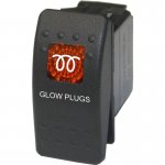
It is helpful to have an LED indicator to inform the driver if the glow plug (GP) relay is in fact closing, so if two conductor wire is pulled from the GP relay, one wire can actuate the coil by grounding the low-side of the coil, and the other conductor can be used to provide power to an indicator LED. I have suggested that a toggle or rocker switch with a legend would make the most sense - an illuminated legend with the ISO 7000-2004,0457 icon:
PreheatIcon.jpg

Would be the most obvious way to inform the driver that the glow circuit is getting power. If the driver left the GP controller wired in and it failed to "no function" (controller just didn't try to turn on the coil), the driver would only have to push the switch to do a manual glow cycle - the function of the switch would be obvious due to tight coupling with the indicator. This is what I proposed to a vendor ("Air On Board") who does custom switches and legends in low volumes (about $15 each):
Glow_Switch.JPG


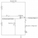
This would be wired as such:
Manual_GP_w_Indicator.jpg

A good candidate location would be next to the 24V gauge in the top right of the dashboard...
 

rsh4364

Active member
1,372
15
38
Location
greensprings ,ohio
Both my 1009s have had ballast resistor removed and are manual push button GPs only,Im not the sharpest knife in the drawer,how would I wire in an activation light?
 

jpg

Member
611
15
18
Location
Boston, MA
Glowplug Indicator LED

As the proud owner of one fried glowplug controller, I wanted to add Warthog's manual switch as a fall-back in case of another failure.

I have read some discussion of using the manual switch even with a functioning glowplug controller. Evidently there are some circumstances when you want more glowplug time than the controller provides. I find this notion confusing, since you don't know when the glowplug controller turns the glowplugs off. You only know when it turns the wait light off. So you might be pushing the button when the controller had the glowplugs on anyway.

I thought an LED indicating when the glowplugs are on would give interesting information about the behavior of the controller. By observing that LED, I would learn how long the controller usually leaves the glowplugs on, both before and after starting. That way, I would know what to do with the manual button, if the controller fails again.

Some have mentioned clicks and the voltmeter providing this info. Perhaps that is true, and I'm just not educated on the technique. I had noticed that my voltmeter reads mid-green for a few seconds after starting, and then it jumps to the green-red line. I was wondering why it took the alternators so long to kick in. Perhaps what I'm seeing is the glowplugs turning off? That would make sense... I'm still a CUCV newbie...

If you only have a manual glowplug button and no controller, the LED indicator would only tell you when you are pushing the button, unless the relay fails. That seems of marginal value to me, but it would do no harm.
 

tim292stro

Well-known member
2,118
41
48
Location
S.F. Bay Area/California
Alternators may have voltage regulators that feature a delay before generation or require a specific RPM before they start generating - it may not be a reliable detection method depending on your total setup.

The LED would tell you that the relay is delivering power, but as such gives you some diagnostic insight as well:

  • If the wait light and glow LED both don't turn on, your voltage may be too low.
  • If the glow LED doesn't turn on and you push a manual over-ride and the LED does turn on, then your glow plug controller or it's wiring may have an issue.
  • If the wait light turns on and the glow LED does not, then the relay or its wiring may be bad.
  • If your glow LED turns on and never turns off even when you turn off the key, the relay contacts have probably welded shut and you are burning up your plugs.

These point coupled with other knowledge of how the diesel runs (i.e. how long it should crank before starting at various temperatures) will give an experienced operator enough to quickly diagnose and potentially repair the starting aid system.
 
Last edited:

tim292stro

Well-known member
2,118
41
48
Location
S.F. Bay Area/California
Hmm... look what came today:
IMG_2818.jpg

Looks like it's maybe just about time to become a SS vendor.

I haven't assembled the switch unit that this actuator clips onto, but once I do it'll do everything the above post #6 says it'll do, plus one additional undocumented feature for bonus diagnostics - just three wires to hook up. I've also been chatting with antennaclimber, while the prototype was being minted, about potentially making this work with the GP card he makes to avoid cutting or pulling any wires through the firewall. Nothing concrete yet, but the gears got turning with this thread - there is probably two ways to go about this without cutting. I already have a beta tester for when I can get the switch body assembled and shipped out to him - so no more volunteers [thumbzup].
 
Last edited:

48cj2a

Active member
311
34
28
Location
Central, IL
I love the switch and wish I would have found one similar at the time I was performing this Mod a few weeks ago.

My Alternative was...I took the Seat Belt/Brake Warning window out and lightly scraped the seat belt lettering off the plastic lens. I then printed a new label on clear tape on my Brother label maker - GLOW PLUGS ! FIRED !.

I pulled the seat belt buzzer out of the fuse box and ran a wire with a terminal pushed in the second terminal from the left of the four and the other end out the firewall to the glow plug side of the GP Solenoid. Now when you push the GP Button (Dorman 86915 Push Button Momentary Starter Switch) you know for sure there is 12v on that side of the relay.

dorman switch.jpggpbutton.jpggpfired.jpg
 
Last edited:

tim292stro

Well-known member
2,118
41
48
Location
S.F. Bay Area/California
That's a fantastic "roll-your-own" effort - I believe you even picked the location for the switch that jpg was talking about in another thread for the control button. My target location is the gauge plate next to the 24V voltmeter, but really it's wherever the vehicle's owner/modifier want to put it...

Nitpicky comment you may disregard at your pleasure - this is for the sake of accuracy to the ISO standard so I'm even hesitant mentioning it at all, the glow icon you have above the button is upside down. Again, just mentioning it because I noticed it - I'm probably the only one who will, so don't trouble yourself changing it on account of me. :beer:

I picked the amber icon window as I wanted to convey an "warning/advisory" event when the glow-plugs fire - red is typically reserved for a "hazard or imminent damage with continued operation" event. As it happens the slick extra function that I'm putting in the switch body has to do with the illumination itself - I'm building in a voltage monitor circuit to the switch body, and with the use of a dual color LED (Amber/Red), I will be able to change from Amber "warning/advisory" indication to a Red "hazard or imminent damage with continued operation" indication if the voltage rises above 14.9V on the 12V half of the glow plug circuit.

This will allow the operator some additional insight to the operation of the glow system that would otherwise be missing - remember that cascade failures result from glow plugs burning out and the voltage rising at the glow plug relay causing more glow plugs to burn out faster. Eventually with all of the glow plugs open the glow plug relay will see the 24V system voltage on the switched side. With the color-changing LED in the switch you would be able to tell that some or all of your glow plugs are not drawing power from the relay. This would close most of the diagnostic loop for the number of failures a glow plug system might have: get an antennaclimber GP card and one of these switches, and you'd be able to diagnose a factory GP system by turning the key to "on" [thumbzup]
 
Last edited:

antennaclimber

Moderator
Moderator
Steel Soldiers Supporter
1,367
949
113
Location
State College, PA
Tim,

Now we will have to make the "GPD-4" card with the GP system diagnostics and a remote start option!

I like your ideas and innovations.
 

Haoleb

Member
197
6
18
Location
Raymond, Maine
I hate to clutter up this thread with more posts but on my truck one of the PO did a manual switch conversion. The controller card is completely gone. What they did was left the pink/black stripe wire attached to one of the coil terminals on the relay and then they tapped off of the 12v power feed on the GP relay (which comes from the resistor bank) ran that to the switch in the cab then back to the other side of the coil on the relay.

The first time I tried to use the switch I turned the key to on and there was a chatter from the relay when I pressed the button much like you would get from too low of coil voltage or something. When I use the manual GP switch with the key off it works fine. I want to wire this thing up properly... It seems like the GP card wiring is un-touched but when I ohm out the pink/black stripe wire to chassis ground I have continuity with the key on or off. It is hard to follow the wiring diagram since it is not all on one page. It would seem to me I should not have any continuity from that pink wire to the chassis since it is supposed to be switched 12v ( BTW this was with both neg terminals on the batt's disconnected.)

Assuming everything is still stock I should just be able to leave the pink/black stripe wire attached and then take the wire they have on the GP relay power feed and just put it to ground to complete the circuit with the switch...
 

PJL

Member
140
6
18
Location
Way south of Seattle, WA
The pink black wire is 12 volts with key on. Use your voltmeter to check it. Not the continuity setting. (Ohms). (You will see continuity because it's finding ground through the other components) The PO wired it wrong. The smaller terminal on the relay that is not connected to the black pink needs to see ground to activate the relay. So instead of connecting your manual switch to 12 volts connect it to ground. It works now with the key off because it's finding a ground through all the other parts in the system. It doesn't work key on because it's seeing 12 volts on both sides of the relay. If the correct wires are still attached you want to ground the light blue one with your button/switch.
 

Haoleb

Member
197
6
18
Location
Raymond, Maine
The pink black wire is 12 volts with key on. Use your voltmeter to check it. Not the continuity setting. (Ohms). (You will see continuity because it's finding ground through the other components) The PO wired it wrong. The smaller terminal on the relay that is not connected to the black pink needs to see ground to activate the relay. So instead of connecting your manual switch to 12 volts connect it to ground. It works now with the key off because it's finding a ground through all the other parts in the system. It doesn't work key on because it's seeing 12 volts on both sides of the relay. If the correct wires are still attached you want to ground the light blue one with your button/switch.
I was unable to test voltage because I have a bunch of other stuff apart I am redoing also. I only got about 1.6 ohm reading which I understand it could go through other components but then usually the resistance would be higher due to the component but it does make sense though that is why I have continuity. I will rewire it up to switch the ground like it should have been. The old wires are still intact but since they ran new wire I'll just use that instead. Thanks for the advice!
 

PJL

Member
140
6
18
Location
Way south of Seattle, WA
On mine I added the button by connecting to the light blue wire at the control module under the dash. No need to go through the firewall. I still have the module and it works. The button is needed on warm starts when the glow plug system does not come on.
 

Haoleb

Member
197
6
18
Location
Raymond, Maine
Well I rewired the relay to switch the ground and it works as expected now! Not sure why they ever did it the way they did in the first place but whatever. At least it was an easy fix!
 

TNMOUNTAINMAN

New member
10
0
0
Location
TN
I am troubleshooting a hard start for my m1009. After reading many threads I did indeed find a broken oring behind the fuel filter. It has the manual conversion. Had it when purchased. After looking at your diagram even with the pushbutton there is still a relay for the glow plugs. Correct? My pushbutton runs to what looks like a solenoid on the firewall. Is the stock setup better than the manual conversion?
 

PJL

Member
140
6
18
Location
Way south of Seattle, WA
The purists will say, and correctly so that the stock configuration works just fine. The relay is necessary because the push button switch can not flow enough current. Think of it like this, using a light switch to turn an electric dryer on and off. The contacts will burn out immediately. The solenoid, or relay has heavy duty contacts inside.

If the current setup works for you and you got it running then leave it. If all the correct components are still there then it wouldn't hurt to hook it back up.
 

RobM36A2

Member
302
9
18
Location
The Netherlands
Just an add-on on the push button conversion:
If you also connect the dark blue wire to ground with the same pushbutton as the light blue wire, your "wait" light goes on also.
Maybe someone already found this out, otherwise, it might be usefull.
 
Top
AdBlock Detected

We get it, advertisements are annoying!

Sure, ad-blocking software does a great job at blocking ads, but it also blocks useful features of our website like our supporting vendors. Their ads help keep Steel Soldiers going. Please consider disabling your ad blockers for the site. Thanks!

I've Disabled AdBlock
No Thanks