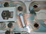
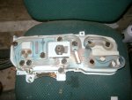
I was testing the cluster circuit "board" on the rear of the instrument cluster (on the kitchen table). The rear left turn signal would come on steady with the headlamps. I noticed three things:
I plan on addressing the problems 1. was already fixed by bending it back in place. I may add a dab of rubber cement under each one to prevent any more of this flimsy business.
On item 2... anyone know a good fix to bridge the cracked copper circuit?
I was simply going to double side cello tape the affected separation..
Last thing. I was testing continuity and found that the incandescent stock 194 wedge bulbs have continuity across the leads; BUT the LED replacements don't have continuity. Is there something about the circuits of the LED bulbs that need electricity before bridging the circuit?
- The bottom most tab that the wiring harness plugs into on the back of the cluster was canted upward and laying on top of the copper tab above it.
- There is a break in the copper circuit to the affected signal lamp
- There is separation in the lamination that sandwich's the copper circuit in one place.
I plan on addressing the problems 1. was already fixed by bending it back in place. I may add a dab of rubber cement under each one to prevent any more of this flimsy business.
On item 2... anyone know a good fix to bridge the cracked copper circuit?
I was simply going to double side cello tape the affected separation..
Last thing. I was testing continuity and found that the incandescent stock 194 wedge bulbs have continuity across the leads; BUT the LED replacements don't have continuity. Is there something about the circuits of the LED bulbs that need electricity before bridging the circuit?


