-
Steel Soldiers now has a few new forums, read more about it at: New Munitions Forums!

M1078 battery help
- Thread starter Rob406
- Start date

More options
Who Replied?- 1,998
- 5,127
- 113
- Location
- Portland, OR
Ohm them to the PPD/LBCD terminal lugs with the battery cables disconnected at both ends.
Ronmar
Well-known member
- 3,791
- 7,359
- 113
- Location
- Port angeles wa
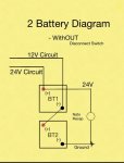
What year truck, A0 or A1?Hey guys. I have an M1078 with no batteries. I’d like to do the two battery swap as outlined on YT by user KLMS. Excellent video. I plan on ditching the nato connection leaving me with four leads. How do I determine which is 12 and which is 24?
Well you can pick a cable, any cable and start hand-over-handing it. Best to lower the spare tire. It is easiest to access the polarity box and shunt, or LBCD(A1) By crawling in where the spare rides…
so you have two 24s, one 12 and one Ground
Ground goes to the front of the starter motor housing and has a strap from there to the drivers frame rail. On an A0 it gets there via an instrument shunt(2 plates with blocks and large stud terminals on each end where wires attach, about 3” long) located between spare and air filter.
24v start goes to the solenoid + terminal on top of the starter.
24v to power panel/from alternator runs inboard to the polarity box or LBCD(A1) to its “24v batt” terminal.
12V runs to the 12V batt” terminal on the polarity box/LBCD between air filter and spare tire.
The easier way is with a volt/ohm meter. Ground and 24v start cables end at their starter terminals… the other 24v and the 12V leads can be measured to the alternator 12 and 24 terminals… about 2 minutes work with the cab up and a length of wire to extend the meter leads to reach starter and alternator terminals…
- 7,691
- 19,714
- 113
- Location
- Charlotte NC
.Thanks for the info guys. Ronmar, it is a 1998.
Are the LBCD terminals labelled?
If I do the volt meter method, what am I looking for for readings?
Welcome to the Outfit!
Kinda like @Ronmar suggested, the best plan is for you to follow the wires that are in your battery box now. We can guess. You can guess on the wires too - but following the wires with your own hands - will help you avoid letting out the magic smoke from the starter or alternator. Those parts aren't cheap so you really want to be sure!

Later on, when you have some battery power you might want to invest a little time in the Technical Manuals (TM's). Yeah, they will bore you to death. There are THOUSANDS of pages too. But, with a little time you will learn the nomenclature and eventually make it possible for you to find part numbers and use the "flow chart" troubleshooting tools in "them there books".
M1078 TM's
Listed below are a number of the TM's for the M1078 trucks. To save them to your computer, right click, select "save as" m1078_TM 9-2320-365-10.pdf TM 9-2320-365-10 for the M1078 series trucks. m1078_TM 9-2320-365-20-1.pdf TM 9-2320-365-20-1 for the M1078 series trucks. m1078_TM...
www.steelsoldiers.com
Welcome to the group and be sure to post some pictures of your new-to-you truck!
Last edited:
Ronmar
Well-known member
- 3,791
- 7,359
- 113
- Location
- Port angeles wa
Your A0 has a polarity protection box not LBCD. Yes the terminals are labeled on the side of the box.
What should you see on a meter? Set it to measure resistance. Leads apart = high resistance(OL?), leads touching = very low resistance(0.1-0.3 ohms).
If you connect one end of a length of wire(8-10') to one battery box cable and the other end to one of your meter leads. You can then touch that other meter lead to the alt 12V terminal, alt 24V terminal, , starter solenoid input terminal and then starter motor ground(front end of motor housing).
Whichever one shows a low resistance circuit identifies the destination of the cable you connected the wire to in the box. Label that cable.
Repeat this test for each mystery cable in the battery box...
Thanks so much Ronmar. I will get at it this friday and will respond with results.Your A0 has a polarity protection box not LBCD. Yes the terminals are labeled on the side of the box.
What should you see on a meter? Set it to measure resistance. Leads apart = high resistance(OL?), leads touching = very low resistance(0.1-0.3 ohms).
If you connect one end of a length of wire(8-10') to one battery box cable and the other end to one of your meter leads. You can then touch that other meter lead to the alt 12V terminal, alt 24V terminal, , starter solenoid input terminal and then starter motor ground(front end of motor housing).
Whichever one shows a low resistance circuit identifies the destination of the cable you connected the wire to in the box. Label that cable.
Repeat this test for each mystery cable in the battery box...
One last question for now. What is the correct way to wire up a trickle charger to the dual group 31 battery set up?
Image is pulled from this site, and is how I plan on wiring the batteries, only without the nato connection.
Image is pulled from this site, and is how I plan on wiring the batteries, only without the nato connection.
Attachments
-
 43.6 KB Views: 15
Ronmar
Well-known member
- 3,791
- 7,359
- 113
- Location
- Port angeles wa
Couple of ways. The A0 has a 12v vampire load, so a 24v charger will not charge the batteries equally. You can get a small 5A balancer and then use a 24v charger or a 12v charger connected to either battery.
you can also get something like a Noco 2 bank charger and connect it to both batteries. This charger will monitor the batteries individually and maintain their charges appropriately.
i used a balancer and have used both float voltage from a solar panel adjusted to 13.1v with a buck converter to add energy when the sun is out, and a 24v automatic charger. Both worked well. I connected the 12v power to the 0-12v battery. is made up for the vampire and the balancer transferred energy to the 12-24 battery as needed, keeping them within 0.1-0.2v.
mine no longer has a vampire load with my reconfiguration, but the balancer is still hooked up with a 24v automatic charger connected.

- 7,691
- 19,714
- 113
- Location
- Charlotte NC
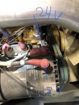
.Guys, this is what Ive got. Everything seems to be painted over - i don’t see labels. I can ohm the leads but i dont know how it will identify which is 12 and which is 24View attachment 896970
What about this?
Here is a picture with words on the PPD.

Courtesy of @country 's outfit.
All you have to do is figure out orientation. (Rotate the picture left or right)

Is the starter 24v ??
Also, is the below correct ?
Also, is the below correct ?
Attachments
-
 76 KB Views: 19
Last edited:
- 7,691
- 19,714
- 113
- Location
- Charlotte NC
.Is the starter 24v ??
Also, is the below correct ?
The starter has its own battery lead going to 24v at the batteries.
On the solenoid, the terminal closest to the block is the positive.
REMEMBER: Following the wires with your own hands is the guaranteed way to wire this puppy.
Guessing sometimes cost big money
Last edited:
Ronmar
Well-known member
- 3,791
- 7,359
- 113
- Location
- Port angeles wa
The starter has its OWN 24v lead to the solenoid on top of the starter. that why there are two 24v terminals in the battery box, one to the top polarity box terminal, and one to the starter solenoid.
The top terminal on the alternator is 24V the next one down/outboard is 12V, and the third terminal is ground with a strap to the frame Like in your picture. There should be labels on it, i haven't seen one without those terminals being labeled…
once you get it all figured out, you need to get in and remove each wire from the polarity protection device one stud at a time and throughly clean and reassemble them. Also do the same for the shunt(seen in your pic, to the left of the PPD). These connections are out in the weather and are notorious for becoming corroded and causing issues…
you can get the Neihoff manuals on their website… here is a shot from the alt manual. They didn’t run the dedicated battery ground on the LMTV install, only the chassis ground strap…
Thank you all. She fired right up with flying colors.
Is a 24 volt charger connected to the positive of batt 1 and negative of batt 2?
Also, having shifting issues. It will stay locked in neutral. I can clear the code and it will then work normally. Once the truck is shut off and tried again it throws the code again. Code 4226
Is a 24 volt charger connected to the positive of batt 1 and negative of batt 2?
Also, having shifting issues. It will stay locked in neutral. I can clear the code and it will then work normally. Once the truck is shut off and tried again it throws the code again. Code 4226
Ronmar
Well-known member
- 3,791
- 7,359
- 113
- Location
- Port angeles wa
Yes on the 24v charger, hook it up like the nato plug in the above drawing.
Ronmar
Well-known member
- 3,791
- 7,359
- 113
- Location
- Port angeles wa
4226 is short to battery N solenoid circuit.
Here is a link to the Allison troubleshooting manual...
Here is a link to the Allison troubleshooting manual...
- 110,614members
- 165,138threads
- 2,323,684posts
- 910online users