M60 tanker
Member
- 32
- 55
- 18
- Location
- Alabama
Does anyone have a wiring diagram for M38A1 with a 100 amp generator. Need one bad.
Steel Soldiers now has a few new forums, read more about it at: New Munitions Forums!


Wonder if there's any difference between the lower and higher output seeming how the 100 amp is for additional equipment useage.Does anyone have a wiring diagram for M38A1 with a 100 amp generator. Need one bad.

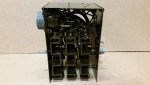
I do have that wiring diagram. What I am needing is a troubleshooting schematicIf you don't have the manual, this is the standard schematic. View attachment 883943
Ok, so knowing that now, what is the issue? I ask only because I can't say I'm aware anything quite like that. Not that there isn't, if there's a TM that has an overhaul procedure for the gennie, it may include what you're looking for then.I do have that wiring diagram. What I am needing is a troubleshooting schematic
What I am needing is the wiring diagram for under the dashboard and ignition switch. All the wires going to the ignition switch are missing there number tags. The wiring under the hood is good. And the generator is changing 26 to 27 volts.Ok, so knowing that now, what is the issue? I ask only because I can't say I'm aware anything quite like that. Not that there isn't, if there's a TM that has an overhaul procedure for the gennie, it may include what you're looking for then.
Oof, so a few things, the schematic I posted will actually give you the info you need for most of that. I don't want to assume your vehicle is still 24V, with only the main power switch, but I will for this. One is power coming in, which is split out to the light switch and horn for constant power from the regulator, so you should have one that reads hot with the switch off. One line out from switch to ammeter that energizes when the switch is on.What I am needing is the wiring diagram for under the dashboard and ignition switch. All the wires going to the ignition switch are missing there number tags. The wiring under the hood is good. And the generator is changing 26 to 27 volts.

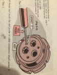
Thank you.Oof, so a few things, the schematic I posted will actually give you the info you need for most of that. I don't want to assume your vehicle is still 24V, with only the main power switch, but I will for this. One is power coming in, which is split out to the light switch and horn for constant power from the regulator, so you should have one that reads hot with the switch off. One line out from switch to ammeter that energizes when the switch is on.
If the generator output is not at 28-32V, there's a field test to determine whether the generator or regulator is faulty. I just went through this a couple months back and am still fighting it after a new generator was put in.
View attachment 883955
Anytime, don't hesitate to ask if there's more that you need. In the M38/M38A1 group on FB, Wes Knettle is usually pretty good about answering the real technical questions as he's been around these machines for years.Thank you.
Do you know the number at the regulator for the ingnitor wire. I think there is no voltage going to the regulator on any of the wires. Wire F going to the regulator does not any voltage and the horn wire that spliced is not there.Recall that the 100 amp system was a kit installed at depot level. The kit would have had an instruction sheet inside the crate. Nobody I know has a copy. Here is what changed with the 100 amp kit on a M38A1 to the best of my recollection: Ammeter is replaced with voltmeter. Ammeter wires (see earlier provided schematic) are abandoned and taped up. A wire needs to be spliced into the ignitor feed wire, This wire will provide excite voltage to the 100 amp regulator. That regulator replaces the 25 amp regulator. At the former 25 amp regulator connector, you will need to separate out wire 10, this needs to be connected to the starter terminal along with the heavy cable from the 100 amp regulator. That should do it.
I think I have found the problem I don't have any voltage on the F wire going into the regulator. Should this wire have voltage all the time or only with the switch on.According to DA Pamphlet 750-33, pin F needs to go hot +24 volts when the ignition switch is turned on.
NDT. I put 24 volts to the Field wire going to the regulator and the generator is still not charging.According to DA Pamphlet 750-33, pin F needs to go hot +24 volts when the ignition switch is turned on.
It has the cylindrical finned top. When I plugged the main connection to the regulator I hear a clicking noise in the regulator.My regulator makes a very audible "clunk" when field power is applied. Is your regulator a simple box or does it have a cylindrical finned top? It's possible your system is shot.
Yes I have the old style rectifier that is in the grill. A bad rectifier will not let a generator charge. Is there anyway to check the rectifierHmm, do you have a selenium rectifier (in the grille) or one with discrete diodes? The selenium looks like a stack of sheet metal plates. They tend to fail due to age. Suggest you replace it with one of the newer types with diodes.