• Steel Soldiers now has a few new forums, read more about it at: New Munitions Forums!

  • Microsoft MSN, Live, Hotmail, Outlook email users may not be receiving emails. We are working to resolve this issue. Please add support@steelsoldiers.com to your trusted contacts.

MEP 002a capacitor

hedgehog69

Member
170
2
18
Location
iowa city, ia
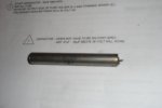
Moving on to next gennie. This question regards the capacitor that is down by the terminal block...below the VR. I have 3 of these so far that the leads have broken off of the ends. I did a google search with info on the capacitor and got nothing. On the paperwork it says "any 47uF - 50uF above 38volt will work".
I did start one gennie few months ago. Today I went to remove capacitor from that machine and saw that it wasn't hooked up. Is this capacitor even necessary for operation of the gennie? Will try to download pic of broken cap.

I did search through eBay and found this listing. Will this work?
47uF 60v Tantalum Capacitor Axial Lead (LOT OF 4) | eBay
 

Attachments

coyote62ny

New member
184
-1
0
Location
sherburne new york
i had to replace the cap in my 003 i have a friend that repairs ham and cb radios i showed it to him he told me it dont have to look like that he gave me two he had 50uf i think they were 100 volt i put one in my oo3 it works great and yes it should be there it is supposed to clean up and even out the ripple in the dc charging system thats what i was told that it did i do know that if it is bad you will get sparks when you hook up the battery cables
 

n1oty

Member
Steel Soldiers Supporter
170
1
16
Location
Taunton, MA
General rule of thumb with capacitors is to use the same type (tantalum, ceramic, etc.), use the same or nearly same level of capacitance (in this case 47 microfarads or close to it), be sure the breakdown voltage is equal to or greater on the replacement capacitor and observe polarity for those capacitors that are polarized (not all caps are polarized).

John
 

ctfjr

Member
83
2
8
Location
central CT
General rule of thumb with capacitors is to use the same type (tantalum, ceramic, etc.), use the same or nearly same level of capacitance (in this case 47 microfarads or close to it), be sure the breakdown voltage is equal to or greater on the replacement capacitor and observe polarity for those capacitors that are polarized (not all caps are polarized).

John

I believe this is VERY good advice. A tantalum behaves very differently than an electrolytic even though they may have exactly the same ratings. Tantalums are much better at killing transient 'spikes' (lower impedance at higher frequencies) where electrolytics are better at ripple filtering.

If I remember correctly a tantalum has a much wider operating temperature range than an electrolytic. I'm not so sure how the latter would stand up to -20F temperatures (or 150F).
 

LuckyDog

Member
394
11
18
Location
Freedom, NH
Here is what I could find out about the capacitor:

IMPEDANCE AT MINIMUM OPERATING TEMP IN OHMS: 68.0
ELECTRICAL POLARIZATION: NONPOLARIZED
FEATURES PROVIDED: HERMETICALLY SEALED CASE
CAPACITANCE VALUE PER SECTION: 50.000 MICROFARADS SINGLE SECTION
NONDERATED OPERATING TEMP: -55.0 DEG CELSIUS MINIMUM AND 85.0 DEG CELSIUS MAXIMUM
DC LEAKAGE AT MAXIMUM OPERATING TEMP: 100.0 MICROAMPERES
NONDERATED CONTINUOUS VOLTAGE RATING AND TYPE PER SECTION: 75.0 DC SINGLE SECTION
TOLERANCE RANGE PER SECTION: -15.00/+50.00 PERCENT SINGLE SECTION
CASE MATERIAL: METAL
CAPACITIVE ELECTRODE MATERIAL: TANTALUM
DISSIPATION FACTOR AT REFERENCE TEMP IN PERCENT: 15.0000
DC LEAKAGE AT REFERENCE TEMP: 10.000 MICROAMPERES
CASE INSULATION MATERIAL: PLASTIC
TERMINAL TYPE AND QUANTITY: 2 UNINSULATED WIRE LEAD
SPECIFICATION/STANDARD DATA: 81349-MIL-C-39006/2 GOVERNMENT SPECIFICATION

To Summarize: NonPolarized Tantalum, 42.5 - 75 microFarads, 75 Volt Rating

Guberment still buys them @ about $130 ea.
 

storeman

Well-known member
1,345
52
48
Location
Mathews County, VA
i had to replace the cap in my 003 i have a friend that repairs ham and cb radios i showed it to him he told me it dont have to look like that he gave me two he had 50uf i think they were 100 volt i put one in my oo3 it works great and yes it should be there it is supposed to clean up and even out the ripple in the dc charging system thats what i was told that it did i do know that if it is bad you will get sparks when you hook up the battery cables
Any chance that your friend might sell a couple or reveal the make and model of the cap so I (and others) could go find it?
Jerry
 

n1oty

Member
Steel Soldiers Supporter
170
1
16
Location
Taunton, MA


Any chance that your friend might sell a couple or reveal the make and model of the cap so I (and others) could go find it?
Jerry

Jerry, you may want to exercise caution until we learn a little bit more about the exact caps that were used in this instance. Besides the very general statement I made earlier about caps, there are other concerns that may be important with respect to this particular cap. I suspect a replacement cap may need to dissipate a fair amount of heat, or what is referred to as "Dissipation Factor". There are de-rating factors to consider as well, but you can generally get around de-rating issues by simply using a cap with a bit higher breakdown voltage rating.

You may want to consult the application sheets put out by a capacitor manufacturer, find one with specs similar to what was posted earlier, then go onto a site like Mouser or Digi-Key and look for that specific cap.

Generally speaking, caps of a particular type get physically larger in order to change capacitance, voltage level and/or dissipation factor (the ability to shed heat). If there is a dramatic size difference between the original cap and the replacement cap, I'd be concerned unless I knew the specs on the replacement.

John
 

NJ_Toolnut

New member
83
0
0
Location
Bloomsbury, NJ
Hi all,

I'm following this thread with a great deal of interest since I get a small spark when I complete the circuit to my batteries and because I also have a good sized dent in my currently installed capacitor. I have not yet tried to use a DMM to confirm it is either shorted or open since my main concern until recently has been to get my unit running again, but I suspect the worst.

I've done a little research and I've found that these tantalum capacitors are quite special in terms of their stability, longevity and environmental tolerance. For this reason, they are used extensively in aerospace applications (nothing is too good for uncle sam, hey?). They currently come in two types, solid and wet. I believe ours may be the wet variety, but they could also be an earlier design. In addition to their above attributes, they also can pack a really large capacitance into a small volume, and they are very expensive, relative to ordinary capacitors. Attached is a data package from Vishay which provides a detailed description of their current line of mil-spec wet tantalum axial lead capacitors. It likely contains more than you would ever want to know, and may provide some good bedtime reading:

View attachment Data on Vishay MIL-SPEC wet tantalum capacitors.pdf

It appears that the mil-spec that LuckyDog cited, 39006/2, may have been superseded, since the Vishay data package does not list it, but does list some that were apparently written later (/09, /21, /22, /25, /30 and /31).

An additional complication is that the technology has changed, and continues to change. For more bedtime reading, see the following:

View attachment twa_series.pdf

Did I say expensive? Here is a link to what is currently available from Mouser. These are not mil-spec, but are similar:

Mouser Electronics - Electronic Component Distributor Tantalum Capacitors - Wet

Prices are per single capacitor, and vary depending on how many are ordered. These may not be quite as good as the mil-spec versions, but I have not been able to find pricing/availability of their mil-spec counterparts.

Here is a look at what is available from TEDSS. These look more like replacements "in kind", since they have similar physical dimensions. I believe they may be mil-spec, but they are even pricier and say "tantalum foil" instead of "wet tantalum":

CL23BL500TNE: 50uF 75V Tantalum Foil Capacitor (Axial Leads)

So given the situation, what to use for a replacement? I'm far from expert on this topic, but my current sense is that although it does not need to be a replacement "in kind", it probably should be a wet tantalum capacitor in order to ensure that it complies with its electical requirements for very long in this operating environment. Like n10ty, I'd be concerned about dissipation factor if there was a dramatic size difference between the original and replacement, since the ability to shed heat is directly related to surface area. On the other hand, the capacitors listed in the Vishay data are all much smaller than the take-out cap, yet some of them have really large dissipation factors. Perhaps dissipation factor is not limited by surface area.

I may replace my cap with one like these:

eBay - New & used electronics, cars, apparel, collectibles, sporting goods & more at low prices

I really like the price, but I'm not happy that they are only rated for 50V.

The other concern I have is that the shedding of leads appears to be a very common failure mode for these caps in this particular environment. I suspect this may be due to environmental vibration setting up resonant frequencies in the leads which results in eventual metal fatigue. I wonder if shrink wrapping the leads would prevent this from happening.

In addition, I would really like to know what the implications are for continuing to run the genset with a failed cap. Do the unsurpressed voltage spikes and ripple from the alternator eventually cook the charging circuit rectifier/voltage regulator, or were these capacitors installed only to provide RF supression?

Best regards,

Stan
 

NJ_Toolnut

New member
83
0
0
Location
Bloomsbury, NJ
Hi deuceaid,

It certainly is calling for a non-polarized (AC) cap. I missed that, thanks for pointing it out.

Do you understand why it calls for a non-polarized cap even though the cap is operating in a 24 volt DC circuit?

Best regards,

Stan
 

LuckyDog

Member
394
11
18
Location
Freedom, NH
It appears that the mil-spec that LuckyDog cited, 39006/2, may have been superseded, since the Vishay data package does not list it, but does list some that were apparently written later (/09, /21, /22, /25, /30 and /31).
MIL-C-39006/2 has been superseded, but not by the /# you reference. Actually, it was canceled without replacement. :mad::mad:

MIL-C-39006/2 is a specification number for " CAPACITORS, FIXED, ELECTROLYTIC (NONSOLID ELECTROLYTE), TANTALUM, (NONPOLARIZED, ETCHED FOIL), 85 DEGREES C (VOLTAGE DERATED TO 125 DEGREES C), ESTABLISHED RELIABILITY STYLE CLR27 "

The Military Part identification numbers (PIN) that will work are:
M39006/02-1219
M39006/02-1247
M39006/02-1275
M39006/02-1303
M39006/02-2317

The "dash #" just specifies failure rate. The higher the dash, the lower the rate (More expense)

I attached a tab-delimited list of part numbers and CAGE codes from the DLA.
 

Attachments

Last edited:

deuceaid

Banned
915
149
0
Location
Yucaipa CA
Toolnut, capacitors can be used for alot of things, to couple circuits, filter out noise, smooth out a power supply, as a bypass to let ac flow around certain parts of a dc circuit... or as a battery to power small loads (hold a charge)....... But I cant tell what this one does
 

coyote62ny

New member
184
-1
0
Location
sherburne new york
these capacitors are aluminum electrolytic capacitors 50uf 100volts they are the same dia. but shorter in length and fit in the origenal cap holder they came from mouser electronics mouser part number 75-tva1343 they are only like 3.00 each the one that is in my 003 has been in there for a year now with no problemsthe new cap. is 1.283 in length one lead out each end i soldered short lengths of wire on mine so i could put crimp on connectors on the wire easyer just heat shrink the solder joint
 

LuckyDog

Member
394
11
18
Location
Freedom, NH
these capacitors are aluminum electrolytic capacitors 50uf 100volts they are the same dia. but shorter in length and fit in the origenal cap holder they came from mouser electronics mouser part number 75-tva1343 they are only like 3.00 each the one that is in my 003 has been in there for a year now with no problemsthe new cap. is 1.283 in length one lead out each end i soldered short lengths of wire on mine so i could put crimp on connectors on the wire easyer just heat shrink the solder joint
the caps i used do have a pos. and neg. sides
As long as the polarity is correct, these will work fine and be a whole lot cheaper.

The capacitor is to "Filter" out the ripple coming of the rectifier. Reduces EMI. The battery don't care about the ripple. Some electronic devices REALLY do, but there aren't any on a standard MEP002/003 setup.
 

n1oty

Member
Steel Soldiers Supporter
170
1
16
Location
Taunton, MA
As long as the polarity is correct, these will work fine and be a whole lot cheaper.

The capacitor is to "Filter" out the ripple coming of the rectifier. Reduces EMI. The battery don't care about the ripple. Some electronic devices REALLY do, but there aren't any on a standard MEP002/003 setup.

I'd really like to see the results of testing done on this non-standard capacitor. For all we know, it may have simply "opened" or "shorted" when power was first applied and now simply sits there with little or no functionality. Furthermore, not all AC filtration is done for purposes of filtering for the gen set's purposes. Much of the suppression is for off gen set EMI/RFI suppression to protect equipment powered by the gen set (ie. the TV's in your house, your computer, etc.).

I have not had the opportunity to study the schematic or look at my MEP and perform any tests. My comments thus far are strictly general comments in regards to capacitors. I suspect the military used tantalum caps here because of there demonstrated longevity, but they could have selected polarized tantalum's if polarization was appropriate. I suspect they could have saved money with polarized tantalum's, too, as non-polarized is less common.

John
 

NJ_Toolnut

New member
83
0
0
Location
Bloomsbury, NJ
I also believe the batteries won't care about the ripple (they essentially act like a large capacitor). I'm more concerned about any detrimental effects a non-functioning capacitor could potentially have on the DC charging circuit rectifier/voltage regulator (expensive to replace).

How much electromagnetic interference (EMI) the alternator and rectifier/voltage regulator produces is an open question, but if their circuits are included in the schematic for these units (at the individual component level) we should be able to get some idea. I plan to look at the schematic riveted to my control cubicle over the weekend (the one in TM-12 is not very legible, even when the Acrobat file is magnified). It might also be very informative to see a scope trace of the signal in this circuit, both with and without a functioning capacitor. I would do this myself if I had an oscilloscope. Since this capacitor is located in the battery charging circuit, it appears to me that whether or not it functions correctly cannot affect the quality of the generator's AC output, but if this DC charging circuit is noisy at radio frequencies due to a non-functioning capacitor this unsurpressed RF radiation could cause an issue for susceptible nearby electronic equipment whether or not this equipment is being powered by the genset.

I'd never heard of tantalum capacitors before I started looking into this, but the ones that most closely match the originals are the ones hegehog69 found (and I linked to) from TEDSS. It appears there are actually three types of tantalum capacitors: solid, wet and foil. The solid ones appear to be smaller in capacitance and breakthrough voltage than the wet or foil varieties. So far, the only ones I've found online that are nonpolar are those of the foil variety. I also believe this particular type of capacitor was used to ensure longevity, as well as functional stability at environmental extremes. Aluminum electrolytic capacitors are a lot better now than they were when these gensets were engineered. I'm not sure that use of a tantalum foil capacitor is absolutely necessary if an electrolytic capacitor will perform the same function in this circuit, given the large difference in cost between the two types.

I don't understand why a nonpolar capacitor was used in a DC circuit. I wonder if a nonpolar capacitor was used because it is intended to surpress EMI that is essentially AC (nonpolar). Since this is a DC circuit, I don't see a polar capacitor with the appropriate voltage rating going "poof" in this circuit unless it is accidentally installed backward (positive to ground), but I'm not sure whether a polar capacitor would fulfil whatever purpose was intended for it in this circuit.

Stan
 

n1oty

Member
Steel Soldiers Supporter
170
1
16
Location
Taunton, MA
I took a quick look at the schematic after work today. The capacitor on the battery charging circuit appears to function primarily to smooth voltage/current output from the voltage regulator. If there is little or no AC on the DC output of the battery charging circuit, I would expect that a polarized electrolytic should work just as well as the original non-polarized cap. On the other hand, if the rectifiers in the battery alternator circuit fail and the alternator puts out more AC, I suspect the polarized capacitor will be toast and it may or may not damage the VR in the process. The design probably called for the non-polarized cap as an extra margin of safety in the event of problems with the battery alternator.

John
 
Top