• Steel Soldiers now has a few new forums, read more about it at: New Munitions Forums!

  • Microsoft MSN, Live, Hotmail, Outlook email users may not be receiving emails. We are working to resolve this issue. Please add support@steelsoldiers.com to your trusted contacts.

MEP-002a only outputting 125v

Cm131

Active member
85
113
33
Location
Nc Charlotte area
Brief history! I bought the machine used. Very cheap! Guy had it for years just sitting in a trailer. Supposedly ran when he put it there. I was able to get the fuel system cleaned.
The phase selector was stuck in the straight up position but I was able to get it freed by oil and tapping.

Then with the help of @Ray @jamawieb @Chainbreaker and others I was guided into finding that the plunger was split in half. Now that all those issue have been fixed I can move on.

I ran the unit today perfectly for a few hours. I then decided to test the voltage so I could prepare to put a load on the system. My voltage regulator by the blower wheel I plan to replace.

Front convenience receptacle works fine.
I was able to measure lugs but I’m only producing 120v from L3 to L0. That’s the only voltage across any combination of the lugs. The switch is set far right 120/220v. I measured the lugs with two different known good meters in every combination I could.

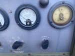
However the panel meter reads almost correct but if I switch the ammeter/voltmeter to the
1
L3-L1
L3
Setting the volt gauges reads around 208
Seems it’s making the power?
And in the
L3
L3-L0
1
Position it reads 120v
Seems correct to my best understanding!!

voltage adjust knob works I can turn the voltage up and down.
I did notice that on my panel door that covers the lugs someone wrote
X over lug 1
L1 over L2
L2 over L3
N over L0
Not sure if maybe someone wired it to only do 120v??

See pic below. Maybe I’m missing something
If anyone has any suggestions or where to begin I would greatly appreciate it. I would
Love to get it figured out tomorrow and begin load testing so it’s ready to power my house. Thanks again!!
FAC31997-EE41-43B2-A525-CAB2B4DA67CD.jpegFFF51C9D-FBF9-4004-B246-CE5FA21165DA.jpeg8220FA5F-BC26-43D2-89B5-4274DBBC4308.jpeg
 
Last edited:

Cm131

Active member
85
113
33
Location
Nc Charlotte area
Worked on the unit today but no change. I did find a couple of wires that were slightly loose so I tightened them back down. Not much at all. Anyways I thought maybe it could be something inside the selector switch since it was stuck when I bought the unit. I sprayed all the wire connection in the side cover as well as all around the switch connections and breaker. I cycled the switch at least 50 times between all three positions but no change. So I decided to try all the positions and see what readings I got.

@1-phase 120/240
Only power was between L3-L0-123v

@1-phase 120v
L1-L0-40v
L1-L3-120v
L3-L0-36v

@3-Phase 120/208
L2-L0-120v
L3-L0-120v
L2-L3-214v

also I adjusted the volts to 123 and Hz to 61.5 with kilowatt meter and it held fine
Batteries were 26.1 not running
27.5 when running
Oil pressure after an hour of running was around 33
I was also able to pull 1600 watts off of the front convenience panel at once. I was running a light and an electric smoker. I was getting concerned with wet stacking as I have about 4-5 hours of runtime but no real load.

if anyone can tell me if these numbers look off or somewhere to look I would appreciate any advise. This is the first military generator I have own. it seems to be making the power just not putting it out in single phase 120/240. Any thoughts??
 
Last edited:

Chainbreaker

Well-known member
1,790
1,968
113
Location
Oregon
No idea about what's causing the issue with your 120/240 output readings. Have you taken the cover of the Reconnection Box off and inspected inside for mouse damage, nests, droppings, etc. (remove the front lower panel just below the load terminals)

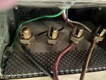
Just for reference here is a picture of my hook-up using SOOW #6 awg cable that goes out to the generator inlet cable connector box on house. You can ignore the wires that exit the top they route to a Spider Box I have mounted on trailer.

Also, note the fix I implemented to mouse proof the AC Reconnection box. Used hardware cloth in back of load terminals to prevent critters from getting inside The hardware cloth is sandwiched between the insulator plate & metal cabinet top & secured by the top screws (it can't vibrate loose). The plastic mesh on front is for whenever house hookup cable is removed for whatever reason to prevent critters from gaining any access.

Of course, you have to figure out & repair any issues with your AC Reconnection box's output first or... find a replacement Reconnection Box & swap it out.


IMG_4193.jpg
 
Last edited:

Ray70

Well-known member
2,581
5,854
113
Location
West greenwich/RI
I would try exercising the AC select switch. I think you have some dirty contacts inside.
I know you initially had a problem with the switch being stuck in 1 position.
I'd also try spraying some Deoxit contact cleaner into the switch through the small gaps where the terminals come out of the switch body.
Exercise it real good and try again.
 

Cm131

Active member
85
113
33
Location
Nc Charlotte area
@Ray70
Thanks for the info. I’ll see if I can locate that particular cleaner. I did exercise it with no change. I have no way of knowing if that’s it or not but to me it seems it’s capable of putting out power just not in the correct manner. Just didn’t know if this was an obvious problem to the much more experience members here.
 

Cm131

Active member
85
113
33
Location
Nc Charlotte area
Could be dirty switch.
Could be a miss wired switch.
Could be a damaged switch.
In 3 Phase, you should get 120 on all three phases.

Start with the first possibility. Then we can try the second.
@Guyfang
Will do the cleaning and exercising the switch more.
alsoI mentioned up above that someone had wrote on the lug box a different configuration so that had me curious about the wiring.
See pic
They have it written
X L1 L2 N
Not sure why?

5B4DDCE3-1176-49A4-A760-F50381A2C646.jpeg
 

Chainbreaker

Well-known member
1,790
1,968
113
Location
Oregon
@Ray70
Is there a way to get to the contacts any better. Those are some small cracks? I’m also assuming the contacts runs the length of the grey housing?
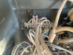
The next time you take the Panel off the AC Reconnection box please take some detailed pictures of the components/wiring inside. It might be helpful for us members here to view & possibly spot something you might have overlooked.

@Cm131
 
Last edited:

Ray70

Well-known member
2,581
5,854
113
Location
West greenwich/RI
To clean it ( and free up a stuck switch as well ) I usually loosen the nuts on the long rods that hold the switch together.
Try to get cleaner in around the little cracks around the terminals as well as between segments as best you can, there's no good openings, but loosening the thru-bolts helps a little.
 

Cm131

Active member
85
113
33
Location
Nc Charlotte area
@Ray70 @Chainbreaker
@jamawieb @Guyfang

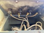
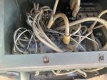
Here are the readings from each lug in all three positions that I got this morning as I wanted to redo the readings to make sure that I had an order to follow and keep up with closely.
I did try to spray more contact cleaner on the switch assembly and the other electrical components.
I am waiting for the Deoxit to arrive tomorrow. I also exercised the switch about 30 times.

1-phase 120v
L-1 to L3 =122.1v

1-phase 120/240v
L0 to L1 =2.5v
L0 to L3= 122.5v
L1 to L3 = 43.2v

3-phase 120/208v
L0 to L1=5.1v
L0 to L2=123.7v
L0 to L3=123.1v
L1 to L2=41.1v
L2 to L3=213.8v
L1 to L3=45.8v

any other thoughts on where to go next??

8C3E1209-801C-435F-BE74-39FCC40886C7.png0D3AE759-8BE2-4C83-B23E-F3430F712CC2.jpeg9C3DF0BD-E8ED-4159-BB5A-1B0A23A905D8.jpegB97D7A8A-8AA4-4560-9C85-559C17521E5E.jpegAF22B83D-9ED8-4061-8C87-1EA224C1199E.jpeg
 
Last edited:

Ray70

Well-known member
2,581
5,854
113
Location
West greenwich/RI
Humm, I assume you're testing at the lugs.
I see masking tape on the wires at the main breaker, as well as the odd markings on the lug cover.
Can you test it in 120/240 mode and test between L2 and L3, should be nothing there, but best to verify.
I'd be curious if there is an incorrect connection in there.
 

Cm131

Active member
85
113
33
Location
Nc Charlotte area
@Ray70
That is correct testing directly at the lugs. I just tested 1-phase 120/240 L2-L3=84.9v
I do believe someone has changed out the an output box as well as the head unit with all the gauges.
 

Cm131

Active member
85
113
33
Location
Nc Charlotte area
So the big Power wires from the breaker to the switch assembly and corresponding lugs seemed to be wired correctly. Looking at the back of the breaker from Left to Right the wires go L3to L3 contact on the switch assembly middle wire is L2 to L2 on the switch assembly and far right wire is L1 to L1 on the switch assembly. LO goes from the switch assembly straight to LO lug.
 

Chainbreaker

Well-known member
1,790
1,968
113
Location
Oregon
Hmmm... doesn't look bad inside though curious as to why there are those 2 rusted screws showing in the front transformer when all the rest are bright silver... odd.

The other thought you mentioned is you think perhaps the AC Reconnection box was changed out with the Control Box. If the individual that did that used a MEP-003a AC Reconnection box, not knowing there is a slight difference between the -002a configuration. IIRC... I believe the winding count of cables passing through the transformers are different # of turns... which can be corrected if true.
 

Guyfang

Moderator
Staff member
Moderator
16,703
23,937
113
Location
Burgkunstadt, Germany
Someone has been in the box. If it were mine, I would take it out and take every wire off, and then hook them back up IAW the wire diagrams. If in doubt, its the only way to KNOW its right. I know its a PITA. But if in doubt..........

Also saw a non standard nut holding load terminal to the non conduction board. Another sign that someone has fooled with it.

This looks like a 10 KW AC output box in post #15. This, Below, is a 5 KW gen set. The wire wrappings !!

1707254093557.jpeg
 
Top