• Steel Soldiers now has a few new forums, read more about it at: New Munitions Forums!

  • Microsoft MSN, Live, Hotmail, Outlook email users may not be receiving emails. We are working to resolve this issue. Please add support@steelsoldiers.com to your trusted contacts.

MEP-003A hook up question

drjconley

New member
174
0
0
Location
merced, ca
My new generator runs great, and the two 110 outlets work fine. I have printed out and read the tm, but I dont fully understand the knob on the full right hand side of the panel that reads voltage and the knob that changes the voltage and phase output.
How would I want to set up the generator to output 220 to feed a panel during a power outage?


Thanks for any help
Jim

M62A2
M813
MEP-003A
 

coyotegray

Member
492
10
18
Location
Oklahoma City
My new generator runs great, and the two 110 outlets work fine. I have printed out and read the tm, but I dont fully understand the knob on the full right hand side of the panel that reads voltage and the knob that changes the voltage and phase output.
How would I want to set up the generator to output 220 to feed a panel during a power outage?


Thanks for any help
Jim

M62A2
M813
MEP-003A
#1 - Have an electrician install a disconnect switch and power inlet box & cable.

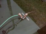
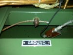
#2 - Have everything correctly grounded. Use a grounding rod at the generator.

The voltage adjustment knob to the far right is to fine tune the voltage.
Put a volt meter on the 110 outlet and you can fine tune the voltage with it..

Ensure that you’re getting 60 Hertz. This is adjusted with the throttle knob. If you idle the generator too low it will damage it.

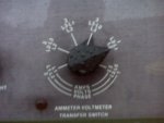
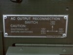
For 120/240 set the "AC Outlet Reconnect Switch" to 120/240 1PH and set the ammeter/voltmeter transfer switch to the setting in the image below.

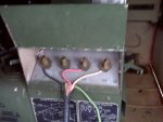
Look at the diagram on the door to the cable connections and compare it to the "AC Outlet Reconnect Switch" and look at how it wired below and you will get the idea...
LO is your common
L1 & L3 each put out 120 so together you get 240.

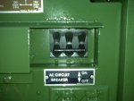
Be sure to have the breaker off until after the generator has warmed up and you verify that your settings are correct and you’re getting the correct output.

Have your electrician verify the output before feeding it to your house.

Anyone else chim in with anything I left out..
Andy...
 

Attachments

Last edited:

Isaac-1

Well-known member
1,970
50
48
Location
SW, Louisiana
Keep in mind I do not own a MEP-003a, but do own a smaller 3kw MEP-701a and have skimmed over the MEP-003a TM.

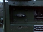
First a little basic theory your generator internally is either a 6 or 12 lead reconnectable generator (the distinction does not matter for our purposes here) these leads are reconnected in various combinations by the voltage selector switch by the circuit breaker (never turn this switch with the unit running). In practical terms what this means is your generator can be set to output 120/208V Wye 3 phase power (used in commercial 3 phase equipment), 120V single phase only power or 120/240V split phase (often also called single phase) used in household electrical connections. On the generator power connector you will find screw down split lugs marked L0,L1,L2,L3, in 3 phase mode all 4 connectors are used, in 120V only mode only 2 are used, and in household 120/240 split phase 3 are used (2 lines and a neutral).

This is where things start to get confusing because these military generators use a different labeling system than residential 120/240 service with its L0 (neutral), L1 (line), and L2 (line). When the selector switch is in 120/240 mode and you are wanting to connect to a residential system (through a transfer switch for safety reasons) then generator L0 connects to house L0 as neutral, Generator L1 connects to House L1 (line ), then Generator L3 connects to house L2 (line) (note the is L3 to L2).

This gives you 120 Volts measured from either line to neutral and 240V measured Line to Line.
Measuring these line to line and line to neutral volts and amps is what the selector switch on the CONTROL PANEL does, for single phase operation you will only use some of the possible settings for measurement.

At this point you may be asking why have both a 120V only and a 120/240 single phase setting on the voltage selector switch, the answer is in 120V only mode you get access to the full output of the generator, in 120/240V mode the output is split into 2 halves with half the output going to each line output and the return coming back through the neutral, in this mode it is more important to balance your loads and so you never draw more than half the total output out of either line (again back to the use of that meter selector switch on the control panel).


Ike

p.s. another important question when wiring a generator up to a home system is the ground bonding of the neutral connection all the references in the TM will talk about grounding L0 (neutral) to the frame and to a ground rod at the generator for stand alone operation. When used with a transfer switch it may be necessary to unbond L0 at the generator from the frame, or use a transfer switch that has a switched neutral if the MEP003 will not run unbonded. The important thing here is that your neutral is only bonded to ground in 1 place (this is usually at the service entrance for a home) this is a point where you should talk over your plans with your local electrical inspector or other electrical professional as code requirements vary from region to region.
 

coyotegray

Member
492
10
18
Location
Oklahoma City
Ike

p.s. another important question when wiring a generator up to a home system is the ground bonding of the neutral connection all the references in the TM will talk about grounding L0 (neutral) to the frame and to a ground rod at the generator for stand alone operation. When used with a transfer switch it may be necessary to unbond L0 at the generator from the frame, or use a transfer switch that has a switched neutral if the MEP003 will not run unbonded. The important thing here is that your neutral is only bonded to ground in 1 place (this is usually at the service entrance for a home) this is a point where you should talk over your plans with your local electrical inspector or other electrical professional as code requirements vary from region to region.
Ike, thanks for that info.. The electrician who did my setup was in a big hurry and I think he didn't pay attention to the fact that I had it hooked up to a ground rod. I also think he was new..

It all makes complete sense. These were designed to be used in the field where the generator was the "service entrance" and so would be the ground location.

Thanks,
Andy...
 

drjconley

New member
174
0
0
Location
merced, ca
I understand everything except the transfer switch. How and why is L3-L1 selected and how does it differ from the other single phase position. I will have my electrician friend read this thread prior to a test run on the house.

Thanks again,
Jim
 

Isaac-1

Well-known member
1,970
50
48
Location
SW, Louisiana
Jim, I am not sure I understand what you don't understand, but here goes a try. Just to clarify the transfer switch is the device you use to wire the generator into your home wiring it lets you select between the utility company power and generator power it is also used to prevent back feeding on the power line and killing a line tech when the voltage would be stepped up by the pole top transformer.

On most civilian reconnectable generators there is no voltage selector switch like the MEP003 has by the breaker, instead a technician would manually reconnect the leads and in the case of 120/240v single phase power they would usually be brought out as leads marked L0, L1,L2 just like you find in household wiring with L0 being neutral and L1 & L2 being the lines/hots.

For some reason, maybe having to do with the selector switch design, the MEP-003 brings 120/240 single phase out on the terminals marked L0,L1 and L3 with nothing on terminal L2 as can be seen in the top middle photo Andy posted. So L0 and L1 are the same your household wiring, but L2 on your house wiring/transfer switch wiringg would be connected to L3 on the MEP-003 wiring lug.
 

Isaac-1

Well-known member
1,970
50
48
Location
SW, Louisiana
Ike, thanks for that info.. The electrician who did my setup was in a big hurry and I think he didn't pay attention to the fact that I had it hooked up to a ground rod. I also think he was new..

It all makes complete sense. These were designed to be used in the field where the generator was the "service entrance" and so would be the ground location.

Thanks,
Andy...

Andy the generator frame can and should be connected to a ground rod, the important thing in most transfer switch installations is that the generator neutral to frame ground strap be disconnected so the only neutral to ground bonding takes place at the service entrance. Again this is in most situations.

Ike
 

coyotegray

Member
492
10
18
Location
Oklahoma City
Andy the generator frame can and should be connected to a ground rod, the important thing in most transfer switch installations is that the generator neutral to frame ground strap be disconnected so the only neutral to ground bonding takes place at the service entrance. Again this is in most situations.

Ike
So the issue isn't having 2 earth grounds, it's having 2 neutral to ground bonds within the same system...correct..? I would still connect the ground cable running from the power inlet to the generator frame that is also connected to a grounding rod at the generator, but the neutral post should not be connected to the generator frame??

Thanks,
Andy..
 

drjconley

New member
174
0
0
Location
merced, ca
Sorry for being a little confusing. I was refering to the ammeter voltmeter transfer switch on the generator itself. I already have a transfer switch on my house, but my current generator is way to small. I can set the generator to the setting andy recommended, but I dont understand what the six different settings represent.

Thanks,
Jim
 

EO2NMCB

Member
643
23
18
Location
DeSoto, MO
I know I maybe somewhat stupid, just ask my wife.

What if your transfer switch amp and volt is set to say L1 which is 3 phase, reconnect switch is set to 120v 1 phase. What is going to be the output? Yes I know not to do that, but I too am confused in the difference between the 2 switches.
 

coyotegray

Member
492
10
18
Location
Oklahoma City
Andy the generator frame can and should be connected to a ground rod, the important thing in most transfer switch installations is that the generator neutral to frame ground strap be disconnected so the only neutral to ground bonding takes place at the service entrance. Again this is in most situations.

Ike
I checked and neutral is bonded to ground at the gen. I e-mailed my electrition to see if this created an issue with how they installed the cut over switch..
Thanks,
Andy..
 

Isaac-1

Well-known member
1,970
50
48
Location
SW, Louisiana
Sorry for being a little confusing. I was refering to the ammeter voltmeter transfer switch on the generator itself. I already have a transfer switch on my house, but my current generator is way to small. I can set the generator to the setting andy recommended, but I dont understand what the six different settings represent.

Thanks,
Jim
The meter reads the combination of volts between the marked L?-L? and the amps of L?, in the position shown on the photo it is measuring voltage from L1-L3 (Line to Line 240V) and amps on L3, the other 1 phase position measures voltage L3-L0 (so would be one of your 120V legs measuring L3 (L2 for your house) to Neutral).

Ike
 

Isaac-1

Well-known member
1,970
50
48
Location
SW, Louisiana
I suspect you could have a potentially dangerous ground loop condition if your neutral wire were to be cut or disconnected. If the electrician says its ok like it is, I would get a second opinion just to be safe.

Ike

I checked and neutral is bonded to ground at the gen. I e-mailed my electrition to see if this created an issue with how they installed the cut over switch..
Thanks,
Andy..
 

saddamsnightmare

Well-known member
3,618
80
48
Location
Abilene, Texas
September 13th, 2009.

Dear Drjconley:

In addition to what coyotegray has said above about the hooking up of your generator and the need for a transfer switch, permit me to emphasize the need for the transfer switch.

The best transfer switch set-up on your house service entrance would or should, ideally use a no-voltage relay. The relay senses the voltage loss on the commercial power line, and if power is not restored , the relay will drop out and stay dropped out. The transfer switch (No Voltage relay actuated) serves to isolate, or disconnect your house circuits from the public power system, and when it drops out it should connect your generator to your house circuits when you cut the generators main braker on its control panel in.

Then you get lights, heat and whatever the generator can drive within its load limits. Some civillian generators are set up to start and automatically connect to your house panel when the transfer drops out.
You may want to have some indicator light installed by your electrician to sense when power is restored on the public utility sideof the transfer switch, so you know when power has been restored (you may live so far back in the hills that they have to pipe sunlight in, I don't know if you have other houses visible close by), so you can cut out your generators main breaker and shut it down, then manually restore your line power at the transfer switch.

The additional purpose of the transfer switch between your house main electrical panel and the public utility and generator driven power supply, is to prevent the public utility, when it restores power, from "Motoring" your generator set. The generator will, if it receives power from the public utility, attempt to act as an electric motor, and if it does, it will generally destroy your generator's engine, as it's governor will not be able to cut back
the engine R.P.M's with the generator motoring it.

Sure, the idea for the transfer switch is also not to fry a lineman working on the public utility's lines, but it also mechanically disconnects your generator and protects it when the power is restored.

Just my two cents worth,:-D

Cheers,

Kyle F. McGrogan
 

jbk

Member
404
5
16
Location
livingston la.
i recently aquired a mep002. i remember i went through this before on hooking up my mep 803 and i removed the nuetral ground strap at the gen. and grounded the frame of the gen. to the ground rod of the house. i was wondering were is the strap is located on the mep002? i guess it might be in the control box
 

Nonotagain

New member
1,444
41
0
Location
Parkville, MD
i recently aquired a mep002. i remember i went through this before on hooking up my mep 803 and i removed the nuetral ground strap at the gen. and grounded the frame of the gen. to the ground rod of the house. i was wondering were is the strap is located on the mep002? i guess it might be in the control box
The ground lug is mounted below the control panel on the frame right beside the slave cable receptacle.
 

Speddmon

Blind squirrel rehabiltator
Super Moderator
Steel Soldiers Supporter
4,640
28
38
Location
Cambridge, Ohio
coyotegray said:
So the issue isn't having 2 earth grounds, it's having 2 neutral to ground bonds within the same system...correct..? I would still connect the ground cable running from the power inlet to the generator frame that is also connected to a grounding rod at the generator, but the neutral post should not be connected to the generator frame??

Thanks,
Andy..
Andy and the rest of you guys. I would have jumped into this discussion earlier, but I have been out of town.

GROUNDING!!!!!!!!! You DO NOT NEED to disconnect the neutral ground of the generator. You also DO NOT NEED to drive a ground rod at the generator! As a matter of fact, you should not drive a ground rod at the generator. The NEC states that only one earth ground shall be installed. This was done at your main service panel when your house was wired and built. You do not drive a second ground rod at the generator, the military does this because these sets are the main power source out in the field. They are not the main power source in your home.

To install them properly, you should be running 4 wires from the generator to the transfer switch/hook-up spot in your house. Two of those wires should be the two "hot" legs of the generator, one wire should be the "neutral" from the generator, and the last wire should be a continuous unbroken ground going back to the grounding bus in the main panel. You could also do as Ike suggested and isolate the neutral bond at the frame of the generator and then drive a second ground rod. This is safe to do, but depending on your electrical inspector you still may have a tough time getting it to pass muster, because as I've stated the NEC specifies only one (1) ground rod shall be driven!

The reason for only having one ground rod is this. If you look at your main electrical panel you will notice that the neutral buss and the ground buss are bonded together, they are essentially (electrically) the same buss. If you drive a ground rod at the generator and do not remove the neutral bond, you now have two (2) pathways for the neutral current to get back to the generator, the neutral wire and the earth ground because of the second ground rod you drove....this is a big NO NO!!!! The current will parallel the two pathways and now the earth ground becomes a current carrying conductor, and as per the NEC this as a violation. The ground shall NEVER be a current carrying conductor. If you feel better doing as Ike sugested, you can go to the trouble of disconnecting the neutral bond on the generator and driving a ground rod, but if you want to go according to the NEC, that is still not a proper installation, is it safe? Yes!

If you have not hooked up the generator yet, save yourself the trouble and hassels, and just run the 4th wire (the ground) back to your panel and do it the easy way. If you have 4 wires going from the generator to your house already, leave the ground wire hooked to the generator frame and remove the one going to the second ground rod (just be sure the neutral bond is connected to the frame).
 
Last edited:
Top
AdBlock Detected

We get it, advertisements are annoying!

Sure, ad-blocking software does a great job at blocking ads, but it also blocks useful features of our website like our supporting vendors. Their ads help keep Steel Soldiers going. Please consider disabling your ad blockers for the site. Thanks!

I've Disabled AdBlock
No Thanks