• Steel Soldiers now has a few new forums, read more about it at: New Munitions Forums!

  • Microsoft MSN, Live, Hotmail, Outlook email users may not be receiving emails. We are working to resolve this issue. Please add support@steelsoldiers.com to your trusted contacts.

MEP-004A & MEP-005A Parallel Cable Assembly

1800 Diesel

Member
768
25
18
Location
Santa Rosa County, FL
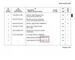
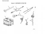
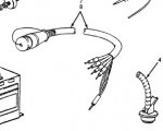
Has anyone ever run a pair of MEP4s in parallel? And related to this question, is an MEP-005A parallel cable the same as what is used on an MEP-004A? I looked in the parts TM for both sets and I didn't see an NSN listed for either cable. Only found a bunch of other numbers in a different column but none found in the NSN column.
 

1800 Diesel

Member
768
25
18
Location
Santa Rosa County, FL
So, since the two partstarget links have two different NSNs, does that mean the cables are not interchangeable? I would have expected the same cable would work with either MEP4 or MEP5.
 

1800 Diesel

Member
768
25
18
Location
Santa Rosa County, FL
I am almost positive that all the 004-009 parallel cables are the same
Thanks--If the connectors fit the MEP4, I'm thinking the same thing. The cable I have came from an MEP5, at least according to fellow I borrowed it from. Might give it a try this week. Just didn't want to damage either of the units...still have a little TM reading to complete also.
 
Last edited:

glassk

Active member
998
4
38
Location
Hampton, GA
It's for gen 1 and gen2 I think, into switch box, they have item 7 and 8 to the one cable maybe it's for the precise set and special relay box, the operators section on it in the 14 manual

I think the ones with electrical speed control can sense a load problem and start the second unit when needed and like Munchies said , the 30's 60's and ones for PU's are going to interchange , but there are several cables and options and the utility one doesn't have.


remember this thread,

http://www.steelsoldiers.com/showth...ator-trailer&p=1411423&viewfull=1#post1411423

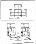
that cable looks like it plugs into that box

Section II..jpg
 

Munchies

Member
417
3
18
Location
Keesler Air force base/ MS
The only thing needed for paralleling is the cable. Load is usually ran right to main lugs on the genset. That box looks like a powerplant box for switching between two gensets for maintanence or malfunction. Basically a manual transfer switch.
 

glassk

Active member
998
4
38
Location
Hampton, GA
Paralleling of precise generator sets
requires that paralleling cables be installed
and the shorting plug in the
lower paralleling receptacle of each
generator set be removed. Paralleling
of utility generator sets requires that
the shorting plugs be installed on all
sets.
WARNING

precise only.jpg

I have the switch box cables in the other post looks like,


1800 Diesel

Member
768
25
18
Location
Santa Rosa County, FL
Munchies,

Already went through that section of the TM...need to make up a 2nd load cable so #2 generator can share the load bank. Will attempt this evening if I get all my other work done today. One concern I have is that I have completed the single phase conversion (via Sewerzuk) on both of these units, but one of them is showing slightly different L1 & L3 voltages. This was covered in an older thread. The TM mentions both gensets need to be at the same voltage but I believe this is referring to having the same reconnection board wiring arrangement, not specific variations between L1 & L3 of each generator.

Prior to conducting the parallel test, I may swap out the VR board to see if that changes anything.
 

glassk

Active member
998
4
38
Location
Hampton, GA


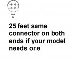
insert 18-4.jpg

Sorry about not knowing the models you have and steady typing, those cables 7 and 8 are the one you need for second load ,
looks like the settings in relay boxes are the voltage and frequency setting s for the permissive relay,
so being able to adjust the two , the oncoming to the online one shouldn't need to swap the vr's just the reconnection boards, same
and transfering or sharing. connections. think when i was looking up the watts transducer I have it was in the governor circuit and know the 15 and 30 Kw units
are the ones to have, I have an 002 to learn on since no diesels in my past, anyway off to mail a package and

the starting if one fails was on an old radr set up ran across,

Aerospace Ground Equipment (AGE), Generators, ECU's, Heaters, etc.
A/E24U-8 - Transportable Power Plant
Specifications: 400 Hz; transportable 60/120kw
Notes: The A/E 24U-8 is a transportable 60/120 KW, 400 Hz Power Plant consisting of two fully-equipped EMU-30/E gas turbine generators and associated distribution equipment mounted on a pallet. The Power Plant will operate in all-weather, global environmental conditions for extended periods. One generator will automatically start if the other one degrades.
Power Output: 30/60/120 KW, 400 Hz, 3-phase, 4-wire, 120/208 VAC or 240/416 VAC.
Weight: 3500 pounds


Munchies

Member
417
3
18
Location
Keesler Air force base/ MS
Glassk. yes the one image is for precision units only, where you are transferring load from one set to another, one coming online to match another.

You still dont need any switch box os other special cables when using utility sets
 

1800 Diesel

Member
768
25
18
Location
Santa Rosa County, FL
Glassk. yes the one image is for precision units only, where you are transferring load from one set to another, one coming online to match another.

You still dont need any switch box os other special cables when using utility sets
I have a parallel cable from an MEP-005A & I believe it's the same as an MEP4 or 6 (as others have said too). I have plenty of load cables suitable for the task. As far as max load amount, for the time being I am set up for about 18KW. When I build my "wet" load load bank rig, I'll be able to test up to 35KW.
 
Top