coyotegray
Member
- 492
- 10
- 18
- Location
- Oklahoma City
Ok, I'm a wrench, not a sparky. I have been going over how to hook up a MEP-016b/MEP-701a for 240v single phase. My head hurts.
I have reviewed related threads and the TMs and get what look to me to be conflicting information.
At one point it states;
"For 120 volt single phase, 120 volt three phase, or 240 volt single phase modes, connect a #6 AWG stranded conductor between the output terminal stud L-2 and frame (ground terminal stud)"
The it states;
In the 240 volt single phase mode, the output
receptacle “NEUTRAL” lead is NOT GROUNDED. When L-2 is
grounded in the 240 volt mode, both leads to the
receptacle will measure a potential with respect to
ground. Serious damage may result if the output
receptacle is grounded. Paragraph 2-5.1.
Then;
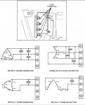
2) For 240 volts,single phase; connect cables to terminals L1 and L2.
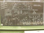
And refers to the attached image..
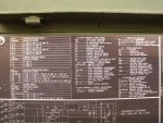
It gives no information I could find about setting the voltage & current setting on the panel..
In another thread I found the following...
"Set the switch to 240 single phase. L1 and L2 are your two hot lines. Install a jumper from S1-5 to S1-6. L0 will now be neutral. Don't use any other switch"
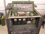
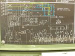
Just where is S1-5 or 6..? I looked all over the inside of the box..
ETA: My intent is to provide household power...
Thanks,
Andy..
Attachments
-
55.8 KB Views: 146
Last edited:


