Catienla,
I would like to add some food for thought here.
My guess would be that you have owned this 004 for a while and the original A11 Exciter / AC Voltage Regulator went to AVR heaven.
Just for clarification, did you convert this 004A from 3 Phase to Single Phase by changing the configuration on the reconnection board? This would help me to better understand your setup.
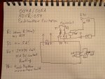
Now, the exciter coil in the 004 is around 3 Ohm DC Resistance. The A11 will put out app. 48 VDC on F1 & F2 when 208VAC are applied to ACVR part of A11.
With this being said, the ADVR-054 manual states:
Excitation Output (F+ to F-)
220V Single phase Continuous 63Vdc 5A = 315 VA
Intermittent 90Vdc 7A 10Sec
Resistance Min.15Ω , Max.100Ω
In comparison the A11 Excitation Output (F1 to F2) :
208V three phase Continuous 48Vdc continues current ?
Intermittent 108Vdc intermittent current?
When we do the math for R = 3 Ohm (Exciter Coil) then the continues current would be I = U/R = 48V / 3 Ohm = 16 Amps DC
and the Power dissipated in the exciter coil would be P = U x I = 768 VA
As we can see, that would be more then double the VA output capability of the ADVR-054
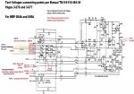
But, the transformer T2 in A11 has a power rating of only app 500VA (de-rated for MIL-SPEC to 300VA)
This tells us two things:
A11 does not put out a DC current to F1 / F2
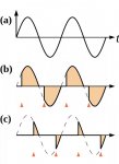
But it is pulsed sinusoidal current
The A11 is and was an absolute master piece of Analog Power Engineering in the mid sixties when it was designed.
At 48 V and 300 VA we will get a maximum current of I = P / U = 300VA / 48V = 6.25 Arms
since this is pulsed, the actual current is around 2.0 A . We tested this a few years ago in this forum here by adding a 3AG fuse on H1 Leg of Transformer T2
any fuse below 2.5A will blow - 3A works
So the exciter is operated by A11 by a pulsed current, limited to about 2A to 2.25A (app 1/3 of 6.25A) with a variable amplitude between 48V to 108V
The excitation is initiated by the S9-1 switch normally open contact and activates K? (forgot which K)
which will provide 24VDC momentarily to start excitation, then the AVR of A11 takes over and regulates the required pulsed (through SCR's and T2) current for the continued excitation utilizing the AC from the generator.
So, I am not sure on how well the ADVR-054 can actually do the excitation because of the low DC Resistance of the Exciter Coil of 3 Ohm
The advantage of the A11 design, which is quite complex, is the capability of controlling the Generator Output Voltage extremely fast and very precise, even if a large load like a Compressor kicks in.
The Governor (Frequency) is a different story.
The Pulsed system vs a continues DC Current system, prevents the saturation of the Exciter Rotor during commutation and the voltage regulation becomes much faster and by far more precise.
Again, this is just food for thought. I am sure you spent quite some time and thought researching an aftermarket AVR and may want to share this with us.
Peter


