• Steel Soldiers now has a few new forums, read more about it at: New Munitions Forums!

  • Microsoft MSN, Live, Hotmail, Outlook email users may not be receiving emails. We are working to resolve this issue. Please add support@steelsoldiers.com to your trusted contacts.

MEP006A Voltage Conversion

ajallow80

New member
23
1
3
Location
Idaho Falls
I have the MEP006A diesel generator currently set at 120/208 V and would like to convert it to 240/416 V.
Looked and the TM but couldn't find any detail instructions on how to do this. The generator is to be used to
operate equipment that require 3 phase 380 volts. The volt meter only gets up to 240 volts max and
that's with the voltage adjust rheostat cranked all the way up. the frequency meter also bare moves.
Any ideas folks? thanks in advance.
 

Scoobyshep

Well-known member
1,090
1,400
113
Location
Florida
I have the MEP006A diesel generator currently set at 120/208 V and would like to convert it to 240/416 V.
Looked and the TM but couldn't find any detail instructions on how to do this. The generator is to be used to
operate equipment that require 3 phase 380 volts. The volt meter only gets up to 240 volts max and
that's with the voltage adjust rheostat cranked all the way up. the frequency meter also bare moves.
Any ideas folks? thanks in advance.
Look at the voltage recommection board (covered in clear plastic has 12 nuts on it) note the arrows on the side. Move the board to the 416 mark and bolt it back down.

Sent from my SM-G973U using Tapatalk
 

ajallow80

New member
23
1
3
Location
Idaho Falls
Look at the voltage recommection board (covered in clear plastic has 12 nuts on it) note the arrows on the side. Move the board to the 416 mark and bolt it back down.

Sent from my SM-G973U using Tapatalk
Ok will try that thank you. I have also noticed that the copper tie bar was cut at the top right hand corner between I believe T11 and T12.
Does that mean it was originally at 240/416 and converted to 120/208? There was also a jumper that connected ( I believe T12 and T2).
 

Scoobyshep

Well-known member
1,090
1,400
113
Location
Florida
Ok will try that thank you. I have also noticed that the copper tie bar was cut at the top right hand corner between I believe T11 and T12.
Does that mean it was originally at 240/416 and converted to 120/208? There was also a jumper that connected ( I believe T12 and T2).
Time out. There should be no jumper.

For clarification from manufacturer this set should produce 120/208 3 phase or 240/416.

If the tiebar is cut between t11 and t12 and t12 is jumped to t2 it has been modified to a low zigzag which produces 120/240 single phase. DO NOT MOVE THE RECONNECTING BOARD. The windings will not be tapped correctly and there is a very high risk of severe damage.


What exactly are you trying to get out of it? 3 phase 416?

Sent from my SM-G973U using Tapatalk
 

ajallow80

New member
23
1
3
Location
Idaho Falls
Time out. There should be no jumper.

For clarification from manufacturer this set should produce 120/208 3 phase or 240/416.

If the tiebar is cut between t11 and t12 and t12 is jumped to t2 it has been modified to a low zigzag which produces 120/240 single phase. DO NOT MOVE THE RECONNECTING BOARD. The windings will not be tapped correctly and there is a very high risk of severe damage.


What exactly are you trying to get out of it? 3 phase 416?

Sent from my SM-G973U using Tapatalk
Yes I'm trying to get 3 phase 416 out of it
 

Scoobyshep

Well-known member
1,090
1,400
113
Location
Florida
Yes I'm trying to get 3 phase 416 out of it
In that case, it needs to be returned back to factory specifications. Then its as simple as moving the board.

*Disclaimer* i have not done this process on a 006. I have on a 004 and 005. There was some control wiring that needed moving. That will probably be the same case on the 006. Need to figure out what belongs where and wire it to the print.

Sent from my SM-G973U using Tapatalk
 

ajallow80

New member
23
1
3
Location
Idaho Falls
And removed the jumper?

Sent from my SM-G973U using Tapatalk
yes the jumper is removed. I figured that restores it back to factory setting but I'm still not getting the required voltage. maybe what's missing is moving the reconnection board. Which I'm so sure where exactly to move it to. So just to confirm, I suppose to remove all 12 mounting nuts and shift the board up (how far up?)
 

Scoobyshep

Well-known member
1,090
1,400
113
Location
Florida
yes the jumper is removed. I figured that restores it back to factory setting but I'm still not getting the required voltage. maybe what's missing is moving the reconnection board. Which I'm so sure where exactly to move it to. So just to confirm, I suppose to remove all 12 mounting nuts and shift the board up (how far up?)
Do you see the arrows on the board? How are they lined up? In the other mod one thing that was moved is for the voltage regulator.

Sent from my SM-G973U using Tapatalk
 

ajallow80

New member
23
1
3
Location
Idaho Falls
Do you see the arrows on the board? How are they lined up? In the other mod one thing that was moved is for the voltage regulator.

Sent from my SM-G973U using Tapatalk
I'm not at the generator currently but I think I see what you are saying now.
will have someone at the location take a closer look
 

G744

Well-known member
Steel Soldiers Supporter
1,707
3,824
113
Location
Hidden Valley, Az
Unless you are in Europe, 416 V is an odd value.

If you adjust the regulator, you should get the standard 277/480V output with the 416V setup.

DDG.
 

ajallow80

New member
23
1
3
Location
Idaho Falls
Unless you are in Europe, 416 V is an odd value.

If you adjust the regulator, you should get the standard 277/480V output with the 416V setup.

DDG.
The generator is overseas in Africa. It's been used in at a bakery.
I bought it in Tacoma WA and shipped it to Africa. I have a non-profit I'm running there.
 

ajallow80

New member
23
1
3
Location
Idaho Falls
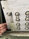
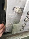
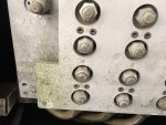
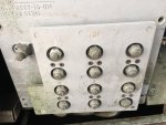
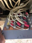
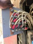
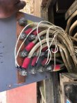
Here is the current configuration of the reconnection board. I suppose I need to shift it up vertically so that the number 4 lines up with the arrow for 240/416 correct?
some pics of the back after replacing the cut copper back and removing the jumper
 

Attachments

Scoobyshep

Well-known member
1,090
1,400
113
Location
Florida
Here is the current configuration of the reconnection board. I suppose I need to shift it up vertically so that the number 4 lines up with the arrow for 240/416 correct?
Correct. BUT knowing that this has been changed to single phase I highly advise you have the control wiring (on the back of the reconnection board) checked vs the wiring diagram. dont wanna blow the regulator.
 

ajallow80

New member
23
1
3
Location
Idaho Falls
Correct. BUT knowing that this has been changed to single phase I highly advise you have the control wiring (on the back of the reconnection board) checked vs the wiring diagram. dont wanna blow the regulator.
Ok I'll see if I can figure that out, I suck at reading wiring diagrams :). Also when you say regulator, you referring to the voltage regulator correct?
thanks again.
 

Scoobyshep

Well-known member
1,090
1,400
113
Location
Florida
Ok I'll see if I can figure that out, I suck at reading wiring diagrams :). Also when you say regulator, you referring to the voltage regulator correct?
thanks again.
yes. In the original procedure I watched and did on 2 units, just the head wiring did change the voltage but as it was loaded the regulator didnt keep up because it was tapped in an odd place and not seeing proper voltage
 

Ray70

Well-known member
2,562
5,795
113
Location
West greenwich/RI
You should go on line and look up the complete single phase conversion procedure. If it was done properly there are 3 more small wire connections that need to be put back in their original positions on the back of the reconfiguration board. These other connections would have been moved to make the gages work correctly in the single phase mode. Here are the wires you need to check. Below is the procedure to go TO single phase, so reverse these connections to get back to 3 phase.
single phase gage conversion.JPG
 
Top