• Steel Soldiers now has a few new forums, read more about it at: New Munitions Forums!

  • Microsoft MSN, Live, Hotmail, Outlook email users may not be receiving emails. We are working to resolve this issue. Please add support@steelsoldiers.com to your trusted contacts.

MEP806B No Start - MPU

RobertoGatos

Active member
Steel Soldiers Supporter
179
19
28
Location
Gilroy, CA
Hello, looking for some input on getting this new to me gen set up and running.

The engine cranks, but fails to start. I've followed the TM trouble shooting as seen by the red arrows:
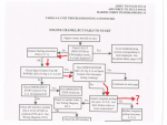
Screen Shot 2020-05-05 at 1.08.28 PM.png


So it seems there is an issue related to the Magnetic Pickup (or MPU as the TM calls it) It appears to be one of the weak links in these units. So I checked it out...

I measured the AC voltage as outlined in the TM, and found it too low, at 0.35V. After adjusting the MPU to the recommended 1.5 turns out, it was still reading too low, at 0.5V. So I screw it in further, to roughly 3/4 turn out and land at 1.55V, just a tad on the high end of a recommended 1-1.5V range. Only problem is that the gen set still won't start, and there is no speed sensor LED illuminating during cranking! Dang! After doing some more research here on SS, some members indicated that it may take as much as 3V to cause the speed sensor to illuminate due to differences in multimeters and the readings they produce. The MPU is now 1/4-1/2 turn out producing 3v and still no LED speed control illumination, and consequently no start.

Here is the MPU adjustment procedure for reference. MPU is located on the bell housing, just behind the fuel filler tube.
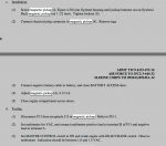
Screen Shot 2020-05-05 at 1.12.07 PM.png


So at this point I just want to hear the thing run, and know I'm not fighting a fuel issue or other mechanical gremlin. I connect 24V DC from the batteries to the injection pump fuel shutoff, follow the normal startup procedure, clearing faults, and the set roars to life. Instantly. I let it run for a minute, turn to "start" again and excite the field, I'm producing power and it sounds great.

IMG_9293.JPG


So at least I know its a runner, just not a starter. Haha

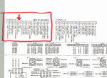
Next I disconnected the J13 junction (the connection at the MPU) and chased the wires back to the P5 junction behind one of the boards above the air filter. The writing all looks good. Pulled off an exterior panel to access the P5 junction to check it for corrosion but is also looks good. Didn't see anything wrong with pin M.

Screen Shot 2020-05-05 at 1.45.01 PM.png


Screen Shot 2020-05-05 at 1.43.33 PM.png


This is where I'm stuck. Still fighting to get the LED speed indicator light to illuminate during cranking, which I believe is preventing the fuel shutoff solenoid from being powered, giving me my "no start"

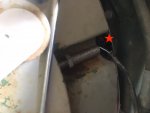
I'm also wondering if I should replace the MPU, (although it CAN supply the correct voltage) considering how far it must be turned in to give the proper voltage range. How exactly does this thing come out? The MPU is so long that the back of the sensor where the wires come out will bottom out against a metal band that wraps the whole flywheel housing. Is there a trick for MPU removal? Access is pretty bad. Red star shows the metal band that causes interference.
IMG_9282.JPG


Other info on the set:

-It was last tested, ran and cleaned 3/26/08 according to the military. This was at 173hr
-Current hours 345
-Unit has an engine rebuild tag of 2/14/08
-Was previously setup on a ROWPU trailer producing 400hz, I've reset to 208V 60 cycle
-Fuel drained, and refilled
-Oil OK
-Coolant level low
-Emergency kill switch has been bypassed by military with a jumper wire
-#28, LED #5 on the backplane module is illuminated red. This is an indicator for low CMOS voltage, which in my research shouldn't cause a no start. Is this correct? Anyone ever replaced the battery?

Any help is appreciated!
 

Attachments

155mm

Chief and Indian
Steel Soldiers Supporter
1,176
388
83
Location
Guymon, OK
so this thread was my red headed step child, a little bit of everything was wrong with it.


RobertoGatos

Active member
Steel Soldiers Supporter
179
19
28
Location
Gilroy, CA
so this thread was my red headed step child, a little bit of everything was wrong with it.


I now have a few cans of electrical contact cleaner on order.
 

Guyfang

Moderator
Staff member
Moderator
16,668
23,813
113
Location
Burgkunstadt, Germany
Hello, looking for some input on getting this new to me gen set up and running.

The engine cranks, but fails to start. I've followed the TM trouble shooting as seen by the red arrows:

Screen Shot 2020-05-05 at 1.08.28 PM.png


So it seems there is an issue related to the Magnetic Pickup (or MPU as the TM calls it) It appears to be one of the weak links in these units. So I checked it out...

I measured the AC voltage as outlined in the TM, and found it too low, at 0.35V. After adjusting the MPU to the recommended 1.5 turns out, it was still reading too low, at 0.5V. So I screw it in further, to roughly 3/4 turn out and land at 1.55V, just a tad on the high end of a recommended 1-1.5V range. Only problem is that the gen set still won't start, and there is no speed sensor LED illuminating during cranking! Dang! After doing some more research here on SS, some members indicated that it may take as much as 3V to cause the speed sensor to illuminate due to differences in multimeters and the readings they produce. (No. The MEP-805B and MEP-806B are adjusted to 1.5 VAC. NOT to 3 VAC. All other sets are adjusted to about 2.5 to 3 VAC. The A models yes. But not the B models. Dont ask why, I simply dont know.) The MPU is now 1/4-1/2 turn out producing 3v and still no LED speed control illumination, and consequently no start.

Here is the MPU adjustment procedure for reference. MPU is located on the bell housing, just behind the fuel filler tube.

Screen Shot 2020-05-05 at 1.12.07 PM.png


So at this point I just want to hear the thing run, and know I'm not fighting a fuel issue or other mechanical gremlin. I connect 24V DC from the batteries to the injection pump fuel shutoff, follow the normal startup procedure, clearing faults, and the set roars to life. Instantly. I let it run for a minute, turn to "start" again and excite the field, I'm producing power and it sounds great.

IMG_9293.JPG


So at least I know its a runner, just not a starter. Haha

Next I disconnected the J13 junction (the connection at the MPU) and chased the wires back to the P5 junction behind one of the boards above the air filter. The writing all looks good. Pulled off an exterior panel to access the P5 junction to check it for corrosion but is also looks good. Didn't see anything wrong with pin M. (these sets, the B models, have real problems with loose connections. I just helped get one running in Hungary, by getting the young man to remove all connections in the control cube, inspecting them, and replacing them. That alone was the problem. Cant say its yours, but if you have not done it, you should. Even the two PITA C-Plugs that hook to the back side of the backplane.)

Screen Shot 2020-05-05 at 1.45.01 PM.png


Screen Shot 2020-05-05 at 1.43.33 PM.png


This is where I'm stuck. Still fighting to get the LED speed indicator light to illuminate during cranking, which I believe is preventing the fuel shutoff solenoid from being powered, giving me my "no start" (This is correct.)

I'm also wondering if I should replace the MPU, (No. But cleaning it would not hurt a bit.) (although it CAN supply the correct voltage) considering how far it must be turned in to give the proper voltage range. How exactly does this thing come out? The MPU is so long that the back of the sensor where the wires come out will bottom out against a metal band that wraps the whole flywheel housing. Is there a trick for MPU removal? Access is pretty bad. Red star shows the metal band that causes interference. (If the MPU is too long to come out, it may not be the standard MPU that fits the set. BUT, it puts out the right voltage. So if it went in, it comes out. I would like to lean over your shoulder, but its at least 6-7 thousand Klicks away. So you have to figure it out. I was told by a CECOM Rep, "If the MPU fits in the hole, its normally going to do the job.)

IMG_9282.JPG


Other info on the set:

-It was last tested, ran and cleaned 3/26/08 according to the military. This was at 173hr
-Current hours 345
-Unit has an engine rebuild tag of 2/14/08
-Was previously setup on a ROWPU trailer producing 400hz, (This is not possible. Your set makes only 50/60 hertz. If it made 400 hertz, it would be a MEP-816B. I think you meant 416 volts? The ROWPU is a 60 hertz set up.) I've reset to 208V 60 cycle
-Fuel drained, and refilled
-Oil OK
-Coolant level low
-Emergency kill switch has been bypassed by military with a jumper wire (Test the switch. If it really bad, add it to your list of things to do AFTER the set runs)

-#28, LED #5 on the backplane module is illuminated red. This is an indicator for low CMOS voltage, which in my research shouldn't cause a no start. Is this correct? (I have seen sets that start with no CMOS power. But if thats the case all the time, not 100% sure.) Anyone ever replaced the battery?
(Contact SS member Peapvc here in SS by PM and ask him. He knows the ins and outs of CMOS battery replacement.)
OK, at last back on line! Last night at about 24:00, after I had written the first two lines here, the internet connection went south for the winter. It seems some stupid drunk managed to hit a commo box in town with his car. At about 18:50 tonight, it came back on.


Open to see what I wrote.
 

RobertoGatos

Active member
Steel Soldiers Supporter
179
19
28
Location
Gilroy, CA
Thanks for taking the time to read through all that Guy, I've got some disassembly and cleaning to do. I'll post back with the results. Gracias!
 

155mm

Chief and Indian
Steel Soldiers Supporter
1,176
388
83
Location
Guymon, OK
Just a side question,

when you bypassed everything and ran the set with 24v going to governor, what hertz was it running? 60 hertz?

the governor controls the hertz, by adjusting the speed of the motor even if only by 20-30 rpm, thats why these machines are so hertz stable.

After you answer, i will explain more depending on your answer
 

RobertoGatos

Active member
Steel Soldiers Supporter
179
19
28
Location
Gilroy, CA
Just a side question,

when you bypassed everything and ran the set with 24v going to governor, what hertz was it running? 60 hertz?

the governor controls the hertz, by adjusting the speed of the motor even if only by 20-30 rpm, thats why these machines are so hertz stable.

After you answer, i will explain more depending on your answer
Yes, i do remember it being stable, +/- 1hz maybe? I can recheck this weekend though.
 

RobertoGatos

Active member
Steel Soldiers Supporter
179
19
28
Location
Gilroy, CA
Well my electrical parts cleaner finally came! I'll be cleaning the connections later some time next week I hope. Will check the Hz an the same time.

Had a question in the meantime though, Is it possible to parallel 2 sets of different KW output? Say a 805b and a 806b for 90 kw? Or only sets of the same output?
 

Wh6czu

Member
52
2
8
Location
Kentucky
Hello, looking for some input on getting this new to me gen set up and running.

The engine cranks, but fails to start. I've followed the TM trouble shooting as seen by the red arrows:

Screen Shot 2020-05-05 at 1.08.28 PM.png


So it seems there is an issue related to the Magnetic Pickup (or MPU as the TM calls it) It appears to be one of the weak links in these units. So I checked it out...

I measured the AC voltage as outlined in the TM, and found it too low, at 0.35V. After adjusting the MPU to the recommended 1.5 turns out, it was still reading too low, at 0.5V. So I screw it in further, to roughly 3/4 turn out and land at 1.55V, just a tad on the high end of a recommended 1-1.5V range. Only problem is that the gen set still won't start, and there is no speed sensor LED illuminating during cranking! Dang! After doing some more research here on SS, some members indicated that it may take as much as 3V to cause the speed sensor to illuminate due to differences in multimeters and the readings they produce. The MPU is now 1/4-1/2 turn out producing 3v and still no LED speed control illumination, and consequently no start.

Here is the MPU adjustment procedure for reference. MPU is located on the bell housing, just behind the fuel filler tube.

Screen Shot 2020-05-05 at 1.12.07 PM.png


So at this point I just want to hear the thing run, and know I'm not fighting a fuel issue or other mechanical gremlin. I connect 24V DC from the batteries to the injection pump fuel shutoff, follow the normal startup procedure, clearing faults, and the set roars to life. Instantly. I let it run for a minute, turn to "start" again and excite the field, I'm producing power and it sounds great.

IMG_9293.JPG


So at least I know its a runner, just not a starter. Haha

Next I disconnected the J13 junction (the connection at the MPU) and chased the wires back to the P5 junction behind one of the boards above the air filter. The writing all looks good. Pulled off an exterior panel to access the P5 junction to check it for corrosion but is also looks good. Didn't see anything wrong with pin M.

Screen Shot 2020-05-05 at 1.45.01 PM.png


Screen Shot 2020-05-05 at 1.43.33 PM.png


This is where I'm stuck. Still fighting to get the LED speed indicator light to illuminate during cranking, which I believe is preventing the fuel shutoff solenoid from being powered, giving me my "no start"

I'm also wondering if I should replace the MPU, (although it CAN supply the correct voltage) considering how far it must be turned in to give the proper voltage range. How exactly does this thing come out? The MPU is so long that the back of the sensor where the wires come out will bottom out against a metal band that wraps the whole flywheel housing. Is there a trick for MPU removal? Access is pretty bad. Red star shows the metal band that causes interference.

IMG_9282.JPG


Other info on the set:

-It was last tested, ran and cleaned 3/26/08 according to the military. This was at 173hr
-Current hours 345
-Unit has an engine rebuild tag of 2/14/08
-Was previously setup on a ROWPU trailer producing 400hz, I've reset to 208V 60 cycle
-Fuel drained, and refilled
-Oil OK
-Coolant level low
-Emergency kill switch has been bypassed by military with a jumper wire
-#28, LED #5 on the backplane module is illuminated red. This is an indicator for low CMOS voltage, which in my research shouldn't cause a no start. Is this correct? Anyone ever replaced the battery?

Any help is appreciated!
I'm having SAME problem.
 

SandBar

Full Time Patriot
756
231
43
Location
GA/FL
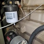
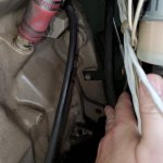
Where is the MPU? I have searched all over and suspect mine is missing or I am going blind. Have another photo of the location, maybe zoomed out? Attachment some photos of mine in case it helps prove its missing. Thanks.

Hello, looking for some input on getting this new to me gen set up and running.

The engine cranks, but fails to start. I've followed the TM trouble shooting as seen by the red arrows:

Screen Shot 2020-05-05 at 1.08.28 PM.png


So it seems there is an issue related to the Magnetic Pickup (or MPU as the TM calls it) It appears to be one of the weak links in these units. So I checked it out...

I measured the AC voltage as outlined in the TM, and found it too low, at 0.35V. After adjusting the MPU to the recommended 1.5 turns out, it was still reading too low, at 0.5V. So I screw it in further, to roughly 3/4 turn out and land at 1.55V, just a tad on the high end of a recommended 1-1.5V range. Only problem is that the gen set still won't start, and there is no speed sensor LED illuminating during cranking! Dang! After doing some more research here on SS, some members indicated that it may take as much as 3V to cause the speed sensor to illuminate due to differences in multimeters and the readings they produce. The MPU is now 1/4-1/2 turn out producing 3v and still no LED speed control illumination, and consequently no start.

Here is the MPU adjustment procedure for reference. MPU is located on the bell housing, just behind the fuel filler tube.

Screen Shot 2020-05-05 at 1.12.07 PM.png


So at this point I just want to hear the thing run, and know I'm not fighting a fuel issue or other mechanical gremlin. I connect 24V DC from the batteries to the injection pump fuel shutoff, follow the normal startup procedure, clearing faults, and the set roars to life. Instantly. I let it run for a minute, turn to "start" again and excite the field, I'm producing power and it sounds great.

IMG_9293.JPG


So at least I know its a runner, just not a starter. Haha

Next I disconnected the J13 junction (the connection at the MPU) and chased the wires back to the P5 junction behind one of the boards above the air filter. The writing all looks good. Pulled off an exterior panel to access the P5 junction to check it for corrosion but is also looks good. Didn't see anything wrong with pin M.

Screen Shot 2020-05-05 at 1.45.01 PM.png


Screen Shot 2020-05-05 at 1.43.33 PM.png


This is where I'm stuck. Still fighting to get the LED speed indicator light to illuminate during cranking, which I believe is preventing the fuel shutoff solenoid from being powered, giving me my "no start"

I'm also wondering if I should replace the MPU, (although it CAN supply the correct voltage) considering how far it must be turned in to give the proper voltage range. How exactly does this thing come out? The MPU is so long that the back of the sensor where the wires come out will bottom out against a metal band that wraps the whole flywheel housing. Is there a trick for MPU removal? Access is pretty bad. Red star shows the metal band that causes interference.

IMG_9282.JPG


Other info on the set:

-It was last tested, ran and cleaned 3/26/08 according to the military. This was at 173hr
-Current hours 345
-Unit has an engine rebuild tag of 2/14/08
-Was previously setup on a ROWPU trailer producing 400hz, I've reset to 208V 60 cycle
-Fuel drained, and refilled
-Oil OK
-Coolant level low
-Emergency kill switch has been bypassed by military with a jumper wire
-#28, LED #5 on the backplane module is illuminated red. This is an indicator for low CMOS voltage, which in my research shouldn't cause a no start. Is this correct? Anyone ever replaced the battery?

Any help is appreciated!
 

Attachments

155mm

Chief and Indian
Steel Soldiers Supporter
1,176
388
83
Location
Guymon, OK
Injector pump side, opposite starter, on flywheel at 1200 position, between motor and generator head
 

Guyfang

Moderator
Staff member
Moderator
16,668
23,813
113
Location
Burgkunstadt, Germany
The TM's are your best friend. Have you downloaded the 24P yet? TM 9-6115-672-24P. Figure 16. Item #2 Sheet 1 of 4. Group 08, Engine accessories. Page # 0017-1.

I wish you luck in your future efforts to fix this or any other gen set.
 
Top
AdBlock Detected

We get it, advertisements are annoying!

Sure, ad-blocking software does a great job at blocking ads, but it also blocks useful features of our website like our supporting vendors. Their ads help keep Steel Soldiers going. Please consider disabling your ad blockers for the site. Thanks!

I've Disabled AdBlock
No Thanks