• Steel Soldiers now has a few new forums, read more about it at: New Munitions Forums!

  • Microsoft MSN, Live, Hotmail, Outlook email users may not be receiving emails. We are working to resolve this issue. Please add support@steelsoldiers.com to your trusted contacts.

Misaligned brake switch

SmartDrug

Well-known member
224
307
63
Location
Saint Charles, IL
I understand how relays work. What I was looking for was where you tucked the wiring, how you deleted the second switch, whether it was removed completely or left in place and bypassed, whether it looked like it would survive being submerged, etc. Whether swiss wiring had an extra neutral to stay out of wars. There are literally dozens of reasons why someone would be curious to see this setup and to have a picture saved for the hivemind of the HMMWV community, you could have just said, no.
 

frauhansen

Well-known member
Steel Soldiers Supporter
305
582
93
Location
switzerland
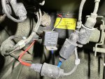
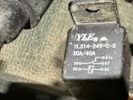
Quite simple... the excitation circuit of the relay is connected to the output of the brake light switch.
To do this, simply make two cables which ideally have the military sockets. A special crimping tool is required for this.
On the switching side of the relay, another cable is then connected to the plugs removed from the gearbox switch using the military plugs/sockets.
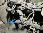
This means that everything remains original on the vehicle side and no cables need to be cut.
Simply hide the whole thing underneath the dash.

But I'll be in the workshop tomorrow anyway, so I can provide you with pictures and a wiring diagram. I can't remember whether the gearbox signal was switched to ON or OFF. So normally closed or normally open.
 

SmartDrug

Well-known member
224
307
63
Location
Saint Charles, IL
So you left the other switch in place, is the arm attached to it or was it uncoupled?

What terminals did you use to attach the Packards to the relay? Did you use a waterproof relay socket and feed into them?

Again, there are dozens of things that you can learn from a picture that go beyond how a relay works.
 

frauhansen

Well-known member
Steel Soldiers Supporter
305
582
93
Location
switzerland
Now it somehow becomes a question of principle ;-)
Does a picture say what you should think about depending on your requirements?
Do I take a watertight relay? Can I see the picture? Rather no. Is that relevant depending on the intended use? Yes.
Have I left the old switch in? What does it matter, it's not working now. But yes, I have. Why dismantle it?
Which terminals did I use? The ones that belong on the relay on the relay side. That depends on the relay used. And on the vehicle side the corresponding military counterpart. (I don't know what they are called)

Please don't hold it against me, it's now 01:30am here. And there is time on your side to have your own thoughts.
 

Milcommoguy

Well-known member
Supporting Vendor
1,749
2,394
113
Location
Rosamond, CA
Now it somehow becomes a question of principle ;-)
Does a picture say what you should think about depending on your requirements?
Do I take a watertight relay? Can I see the picture? Rather no. Is that relevant depending on the intended use? Yes.
Have I left the old switch in? What does it matter, it's not working now. But yes, I have. Why dismantle it?
Which terminals did I use? The ones that belong on the relay on the relay side. That depends on the relay used. And on the vehicle side the corresponding military counterpart. (I don't know what they are called)

Please don't hold it against me, it's now 01:30am here. And there is time on your side to have your own thoughts.
Ding Ding Ding.... Back to your corners. Time out............
I don't see the drawing showing the transmission TC circuit with the normally closed contacts for the #810A & 810B wires, the little round plug associated with the TC switch left side of the failing or troubled switch to align. Labels are a bit confusing too. Pretty colors.

Relay coil would be... one side to ground and the other to 74B. Look closely for it on the right side of dual switch. Stated this my post above 15 & 16

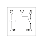
Sooo... Pin 85 to tap HumV wire 74B located on switch.
Pin 86 to ground. A good one.
Pin 87 to TC connector wire 810A
Pin 30 to TC connector wire 810B

big realy.png
BE SURE to have a 24 volt unit / COIL

This is my interpretation of the thread with funky stop and TC disengagements. If I misunderstood the problem.... I will take a time-out... OR this might just be the next Camotek product.

I ate my crayon for lunch, CAMO
 
Top