• Steel Soldiers now has a few new forums, read more about it at: New Munitions Forums!

  • Microsoft MSN, Live, Hotmail, Outlook email users may not be receiving emails. We are working to resolve this issue. Please add support@steelsoldiers.com to your trusted contacts.

Restoring the Deep Water Fording Kit

Ajax MD

Well-known member
1,569
1,414
113
Location
Mayo, MD
My truck was a Marine truck that was re-engined to a 6.5L in 2002. It was originally equipped with the fording kit.

It seems that during the reset, the kit was removed or bastardized. The most obvious differences are the short intake and exhaust stacks. These should obviously be the tall versions.
I discovered that the fording valve is still installed in the cab. Yesterday, I figured out that I still have the power steering cap vent line.
This morning, I was going over the parts list in the TM and it seems that I still have the fording dip sticks for the oil and transmission fluid levels.

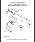
I'm a bit confused on the "sensor cup" and "vent valve", items 12 and 18 in Figure 399. Where are these mounted?
Next, does the vent line on the hydroboost go back to the system of hoses and "T" fittings in Figure 399?
Lastly, does the fording system not pressurize the transmission or transfer case? Or is this done via the power steering system?

Really lastly, is there a way that I can test the system? Should I feel some positive pressure at the P/S cap vent line if I flip the lever in the cab?

If I have enough of the pieces, I will buy or fabricate the missing components and restore the system. If I'm missing too much, I'll just skip it.
 

Crapgame

Well-known member
635
329
63
Location
Navarre, FL
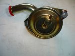
On the block top, right side you have the yellow zinc plated CDR Crankcase Depression Regular Valve, the DWF CDR has an extra horn on the top for the vent line that runs up the side of the intake stack. The DWF CDR is probably the 2nd or 3rd most expensive component of the DWF Kit, behind the DWF Exhaust. If you still have that you may be in good shape, although it does have a valve membrane inside that can go bad, dry out with age/temp. A replacement is about $220. The RH side B Pillar DWF Sensor Cup is about $25-40.


Fording CDR Valve.jpg

Here's a link to DWF Kit installation instructions and the leak test can be found in 3-14:
 

Ajax MD

Well-known member
1,569
1,414
113
Location
Mayo, MD
On the block top, right side you have the yellow zinc plated CDR Crankcase Depression Regular Valve, the DWF CDR has an extra horn on the top for the vent line that runs up the side of the intake stack. The DWF CDR is probably the 2nd or 3rd most expensive component of the DWF Kit, behind the DWF Exhaust. If you still have that you may be in good shape, although it does have a valve membrane inside that can go bad, dry out with age/temp. A replacement is about $220. The RH side B Pillar DWF Sensor Cup is about $25-40.


View attachment 798401

Here's a link to DWF Kit installation instructions and the leak test can be found in 3-14:
Awesome, thanks. This part seems familiar to me from past excursions into the engine bay. I'll pop the hood this afternoon or weekend and check for those parts.

Then, I'll need to pull the doghouse off and check to see if the valve/switch in the cab is actually connected to anything. It would be weird (but lucky) if all the parts were intact except for the intake and exhaust stacks.
 

AAVP7

Well-known member
217
262
63
Location
Dortmund, Germany
Sorry to interfere here, but I´m pretty sure the line from that extra horn on the CDR valve does NOT go up the intake stack. The extra horn is connected to the sensor cup. The air pressure being trapped inside the sensor cup when deep fording acts upon the mebrane inside the CDR, and directs more overpressure to the vent system.

The line going up the intake stack is the vent line for your fuel tank, passing through that little filter behind your coolant reservoir.

Those DWF kit instructions are sometimes not very clear.
 

stucazz74

New member
5
2
3
Location
Central Florida
My truck was a Marine truck that was re-engined to a 6.5L in 2002. It was originally equipped with the fording kit.

It seems that during the reset, the kit was removed or bastardized. The most obvious differences are the short intake and exhaust stacks. These should obviously be the tall versions.
I discovered that the fording valve is still installed in the cab. Yesterday, I figured out that I still have the power steering cap vent line.
This morning, I was going over the parts list in the TM and it seems that I still have the fording dip sticks for the oil and transmission fluid levels.

I'm a bit confused on the "sensor cup" and "vent valve", items 12 and 18 in Figure 399. Where are these mounted?
Next, does the vent line on the hydroboost go back to the system of hoses and "T" fittings in Figure 399?
Lastly, does the fording system not pressurize the transmission or transfer case? Or is this done via the power steering system?

Really lastly, is there a way that I can test the system? Should I feel some positive pressure at the P/S cap vent line if I flip the lever in the cab?

If I have enough of the pieces, I will buy or fabricate the missing components and restore the system. If I'm missing too much, I'll just skip it.

Hello, I have a M1151A1 that seems to have many of the Fording Kit parts still present. Can you send me the part list and diagrams that you referred to so I can verify what . where and how some things go? Thanks, Chris
 
Last edited by a moderator:
Top
AdBlock Detected

We get it, advertisements are annoying!

Sure, ad-blocking software does a great job at blocking ads, but it also blocks useful features of our website like our supporting vendors. Their ads help keep Steel Soldiers going. Please consider disabling your ad blockers for the site. Thanks!

I've Disabled AdBlock
No Thanks