• Steel Soldiers now has a few new forums, read more about it at: New Munitions Forums!

  • Microsoft MSN, Live, Hotmail, Outlook email users may not be receiving emails. We are working to resolve this issue. Please add support@steelsoldiers.com to your trusted contacts.

Timing Marks -0- on Crankshaft and Camshaft Gears

Texjun

New member
47
0
0
Location
Dish Texas
Timing Marks

I am confused can someone please help?

My M37 Dodge 230 Engine was running fine before I removed it.

While engine is out of the truck I removed the Timing Cover to replace the seal and gasket.

I noticed when the #1 cylinder is at Top Dead Center the Crankshaft timing mark Zero -0- was directly between Crankshaft and Camshaft gear centers but the Camshaft Gear Zero -0- was 180 degrees of where the TM 9-1840A Fig. 88 page 99 shows that they should be directly between Crankshaft and Camshaft gear centers.

Crankshaft Gear -0- was correct but Camshaft Gear was 180 degrees of where figure shows it.

I removed the three bolts from the Camshaft gear and removed it and the chain.
I tried the Camshaft Gear in different positions but I think it only fits in one position, IS THIS CORRECT?

I followed the instructions from TM 9-1840A Fig. 88 page 99 and realigned the Timing Marks per the picture in Figure 88 and tightened up the Camshaft Gear.

I rotated the Crankshaft Clockwise several revolutions and watched the #1 Intake Valve Open and the close and when # 1was at TDC and looked at timing marks and they were back to where I started, Camshaft timing mark Zero -0- at the complete opposite 180 degrees.

Is this just a Set Up Point and will not repeat itself ?

TM is not clear on this point.

Please someone HELP
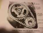
M37 Timing Marks Fig 88 001.jpg
 

Roller

Active member
Steel Soldiers Supporter
184
51
28
Location
North Lake, WI
If you have the timing gears aligned per the manual and as shown in your photo, that is correct.

Frank
 

Texjun

New member
47
0
0
Location
Dish Texas
Yes I did the realignment per Fig 88, but once I put everything back together and turn the Crankshaft Clockwise through several times and each time #1 cylinder is back to TDC the Camshaft -0- Timing Mark is 180 degrees from where it was during realignment procedure.

Is this correct?
 

Roller

Active member
Steel Soldiers Supporter
184
51
28
Location
North Lake, WI
Yes it is correct, don't confuse camshaft timing with ignition timing. The camshaft turns half of what the crankshaft turns in a revolution.
In other words, if you start with the marks aligned as in the photo and turn the crankshaft 1 revolution the mark on the cam will be 180 degrees from the mark on the crankshaft gear. If you put a degree wheel on the engine you can check valve timing.

Frank
 

rosco

Active member
Steel Soldiers Supporter
2,102
28
38
Location
Delta Junction, Alaska
It seems like it could be timed 180* off. Then you use #6, instead of #1. Another common error, is that one mistakes the rotation of the distributer, thinking it rotates the other way around, and the wires to the plugs are on backwards.
 

Texjun

New member
47
0
0
Location
Dish Texas
Thanks to Mr. Charles Talbert at M Series Rebuild LLC my confusion and problem is solved Thanks Charles

Charles wrote "When the 2 dots on the sprockets are directly aligned and next to each other, that is TDC on the compression stroke for #6 cylinder. When the dots are opposing each other the max distance, yet are directly aligned, that will be TDC on the compression stroke for #1. The easiest way to assemble it all and be in time is to match the dots in the closest position with the chain off. You can’t install either the cam sprocket or the crank sprocket wrong as they will only fit 1 way. Once you have the dots aligned; remove the cam sprocket and install the chain and sprocket as an assembly being very careful not to let the camshaft rotate in either direction during the process. You can double check it like this, remove the push rod covers so you can see the valve action. Once the chain is on rotate the crank right a ways from 0, then back to the left while watching the valves on #1 and #6. The valves that DO NOT MOVE (should be on #6) while rotating back and forth in both directions; that cylinder is on the compression stroke. In this position, you will notice both valves on #1 will be rocking open and closed as you rotate the crank. That means #1 is on the exhaust stroke. #1 and #6 piston will always be up at the same time; the thing is this, timing must be set when #6 is at TDC on the compression stroke. In this position #1 is at TDC, BUT it is on the exhaust stroke. When the marks on the sprockets are opposed, yet are aligned 180 degrees from each other, then #1 is on the compression stroke and #6 is on the exhaust stroke. Then the oil pump shaft must be meshed correctly with the drive gear on the camshaft and the distributor installed correctly to get timing exactly correct. At this point the engine should start at which time you can use a timing light to set timing at exactly 4 degrees BEFORE TDC for perfect timing advance."
 
Top
AdBlock Detected

We get it, advertisements are annoying!

Sure, ad-blocking software does a great job at blocking ads, but it also blocks useful features of our website like our supporting vendors. Their ads help keep Steel Soldiers going. Please consider disabling your ad blockers for the site. Thanks!

I've Disabled AdBlock
No Thanks