• Steel Soldiers now has a few new forums, read more about it at: New Munitions Forums!

  • Microsoft MSN, Live, Hotmail, Outlook email users may not be receiving emails. We are working to resolve this issue. Please add support@steelsoldiers.com to your trusted contacts.

Volt Meter Connections for Rosscommon Conversion Single Alt.

Brogman

Member
102
3
18
Location
Noblesville, Indiana
I have a new 12volt volt meter. Tried using the original connections after the rosscommon conversion. Doesn't work no power to the Gray wire. Would like to get this working properly. Can anyone help?
 

Brogman

Member
102
3
18
Location
Noblesville, Indiana
Thanks rsh4364 said with a laugh. I was hoping to install it to the original wiring connections. Already have the light working using the original wires. Do you have a suggestion for a + that is only active with the key on? I could use one of those splice connectors and run a wire from it to the meter.
 

doghead

4 Star General /Moderator
Staff member
Super Moderator
Steel Soldiers Supporter
26,246
1,178
113
Location
NY
Have you looked at the TM for the schematics?
 

cucvrus

Well-known member
11,473
10,427
113
Location
Jonestown Pennsylvania
Thanks rsh4364 said with a laugh. I was hoping to install it to the original wiring connections. Already have the light working using the original wires. Do you have a suggestion for a + that is only active with the key on? I could use one of those splice connectors and run a wire from it to the meter.
Check out the fuse box. It has a couple of open areas that are switched off and on with the key. Use an in line fuse and it will give you a switched power source. I hope that helps.
 

Warthog

Moderator
Super Moderator
Steel Soldiers Supporter
13,774
232
63
Location
OKC, OK
The CUCV Helpful Threads sticky has a thread for the diagram of the fusebox. It tells you what connection is controlled by what.
 

Brogman

Member
102
3
18
Location
Noblesville, Indiana
Thank you gentleman. Is there a reason that the original wiring won't work. I know it was set up for 24 volts so I assume there is something there that might cause it not to work.
 

Warthog

Moderator
Super Moderator
Steel Soldiers Supporter
13,774
232
63
Location
OKC, OK
Was the gauge working before?

if the conversion is done properly the 24v which feeds the voltmeter (through the voltmeter relay) should now be feeding 12v to the meter plug.
 

Brogman

Member
102
3
18
Location
Noblesville, Indiana
Thank you Warthog. The meter was dead. I thought it might be the meter and not the wiring. I thought there may be a reason the new meter wouldn't work due to diodes or something for the 24 volt system. You answered that question. I will "try" to figure out the wiring diagram and hopefully fix the stock wiring if not will try something else. I need to figure out which relay is the volt meters and see if that is the problem. My Gen 2 light works so will get a relay and then unplug each relay to see which one powers the gen 2 and that would tell me which one is the volt meter relay. With the key off while plugging and unplugging.
 
Last edited:

Warthog

Moderator
Super Moderator
Steel Soldiers Supporter
13,774
232
63
Location
OKC, OK
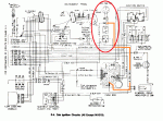
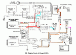
E-04 voltmeter.gifE-09 GEN 2.gif

The voltmeter relay will have the white, black and pink/black wires on the connector.

GEN2 has the brown, brown/red and pink/black wires
 
Last edited:

Warthog

Moderator
Super Moderator
Steel Soldiers Supporter
13,774
232
63
Location
OKC, OK
Just to clarify, at the connector, the orange wire will be hot at all times and the black wire is the ground which is controlled by the relay.

The gray wire is the power feed for the VM and heater control lights.


**** Corrected incorrect intel from the wiring diagrams ****
 
Last edited:

Brogman

Member
102
3
18
Location
Noblesville, Indiana
Warthog your help is greatly appreciated. Checked the connector for the relay and I do have power to a pink/blk stripe wire with the ignition switch on. There is a black/white stripe wire and 3 other black wires going into the connector. 2 of the black wires come together to the same connector to the relay. Funny thing the gage light worked some times I had to wiggle the wires and the gage didn't. I put in a new relay. It did click when ignition turned on. Now the gage still has no power to the gray wire that was connected to it but the orange wire to the light connector has power all the time. Another wiring harness I have to cut open and find the problem. I couldn't even come close to figuring this out with out the help and information from Steel soldiers. I am working on the front axle and drive line replacing ball joints/tie rod ends/bearings/seals/hubs/lockinghubs/rotors/brakes/lines etc. And this hopefully is the last electrical problem to be fixed for now.
 
Last edited:

cpf240

Active member
1,479
5
38
Location
Free in Northern Idaho
Warthog your help is greatly appreciated. Checked the connector for the relay and I do have power to a pink/blk stripe wire with the ignition switch on. There is a black/white stripe wire and 3 other black wires going into the connector. 2 of the black wires come together to the same connector to the relay. Funny thing the gage light worked some times I had to wiggle the wires and the gage didn't. I put in a new relay. It did click when ignition turned on. Now the gage still has no power to the gray wire that was connected to it but the orange wire to the light connector has power all the time. Another wiring harness I have to cut open and find the problem. I couldn't even come close to figuring this out with out the help and information from Steel soldiers. I am working on the front axle and drive line replacing ball joints/tie rod ends/bearings/seals/hubs/lockinghubs/rotors/brakes/lines etc. And this hopefully is the last electrical problem to be fixed for now.
Please re-read Warthogs post above yours. The orange wire is hot at all times and goes to the gauge, not the light. The black (not the white/gray) wire is the ground wire for the gauge, and is switched via the relay. The stock gauge is isolated from the rest of the dash, so does not get its ground connection via its mounting, as is common with many gauges. The relay provides the ground path when the key is on.
 
Last edited by a moderator:

Warthog

Moderator
Super Moderator
Steel Soldiers Supporter
13,774
232
63
Location
OKC, OK
No need to cut open the wiring.

As cpf240 said the black (not the white) wire is a ground. You will not get a voltage reading from it. You can however see if it is providing a ground path. Energize the relay and use an ohm meter on the black (not the white) wire and a ground to see if the ohms go to zero.

Sounds like the ground wires (black wires on the relay connector) are not making good contact all the time.That is why when you wiggle them the light comes on.

Check the common ground point at the emergency brake pedal. See the picture in the link. You can check the ground wires by putting an ohm meter on the black wires and a clean ground.

http://www.steelsoldiers.com/showthread.php?120289-CUCV-Electrical-Ground-Locations

relays.jpg
 
Last edited:

Warthog

Moderator
Super Moderator
Steel Soldiers Supporter
13,774
232
63
Location
OKC, OK
Okay I found where the confusion is. I was giving you bogus instructions.

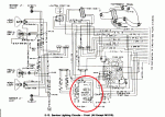
The wiring diagrams are wrong. It is showing the ground wire for the voltmeter as being white. The true color is black (or brown , can't tell from the picture). It is the "other wire" in the two pin connector with the orange wire. (I have never had to work on this so I never looked at the diagrams).

The gray wire is the hot wire for the voltmeter light and will only be hot when the headlight switch is on.

wires.jpgE-13 - VM light.gif
 
Last edited:

Brogman

Member
102
3
18
Location
Noblesville, Indiana
You gentleman are the best. I will try to digest this new information. I wired the light and gage exactly as I found them wired to the old gage and old gage light. The wires I wiggled where the ones to the light up in the dash. I didn't mess with the relay wires. All I did was check voltage at the relay plug and replaced the relay. The light did work with the light switch before I replaced the relay wired as shown, I guess the orange wire was wired wrong and the black ground wire wasn't grounding until I wiggled it. Don't know. Thanks for all the help.
 
Top
AdBlock Detected

We get it, advertisements are annoying!

Sure, ad-blocking software does a great job at blocking ads, but it also blocks useful features of our website like our supporting vendors. Their ads help keep Steel Soldiers going. Please consider disabling your ad blockers for the site. Thanks!

I've Disabled AdBlock
No Thanks