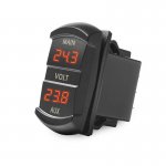
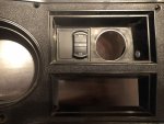
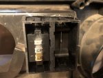
I've searched through all the threads on this site and on the interweb, but could still use some help on the best way to wire in a new dual digital voltmeter like the one pictured below.
I know it is a cheap part, but giving it a try as I'd like to mount a tach in the old spot for the original voltmeter (that wasn't working). I've got a backup ISSPRO 24V unit and all the threads on here to install it if I have any issues.
TechnoWeenie is the only one who I've seen installed the same VM. He tied into the original 24V wire lead from the old VM and ran 12V from the ignition wire. As I understand it, this will give me the 12V reading from the front battery and the 24V combined reading. This sounds good to me, but also wanted to know:
1) What gauge wire should I use?
2) Can I use the negative lead from the old VM wiring too? -OR-
3) Should I just run a shared negative lead to ground somewhere on the frame?
Electrical is my weakest knowledge, so wondering how I should install to get the most accurate reading with this setup.
I appreciate any ideas/help!


