• Steel Soldiers now has a few new forums, read more about it at: New Munitions Forums!

  • Microsoft MSN, Live, Hotmail, Outlook email users may not be receiving emails. We are working to resolve this issue. Please add support@steelsoldiers.com to your trusted contacts.

Gen 2 wire plug readings help

82ABNMP

Active member
Steel Soldiers Supporter
556
53
28
Location
Winston Salem NC
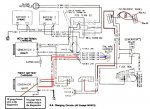
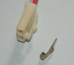
I have installed both newly rebuilt (correct) Gen 1 and Gen 2 on my 1008, and took these readings as suggested in other threads from the 2 wire plugs that go in back of both Gen 1 & Gen 2:


Gen 1 : Red wire :Key off ---11.99v Key On------10.78v
Brown wire :Key off----0v Key On------10.75v


Gen 2 : Red wire :Key On------1 .v Key Off -------1 .v
Brown wire :Key On--- 0v Key Off ------ 1 .v

I have never had a Gen 1 light function in this truck, bulb is tested and good.
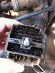
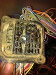
Gen 2 light comes on with key in the "on" position. From other posts I know to look in the cab wiring for problems but would like to know where to start.

Thanks, David
 
Last edited:

82ABNMP

Active member
Steel Soldiers Supporter
556
53
28
Location
Winston Salem NC
thanks

Yep, Gen II light is on and goes off as it should. Been talking to John from CUCV electric and we are thinking the same thing. I will check the brown wire on Gen I back to the bulb in the gauge cluster BTW (great guy and great support!!) :beer:

David
 

Barrman

Well-known member
5,216
1,685
113
Location
Giddings, Texas
If you have John working on the problem, then you don't need our help.

You write that you have a GEN I problem, yet GEN II is giving the bad readings. Or am I reading things wrong?
 

82ABNMP

Active member
Steel Soldiers Supporter
556
53
28
Location
Winston Salem NC
More than one problem

I posted this before I got into contact with John. Since then:

I have more than one problem. Gen II 's under dash relay was bad. That's fixed.

Volt meter was pegged out into the overcharge red range with the key in the "on" position...bad resistor. It read 86.5 on the ohm meter. New one on the way.

Only problem left is the Gen I light is still not coming on. I have cleaned the bulb contacts, bulb housing and the gauge film where it contacts the bulb housing. Sill dark. So that's where I am for now.

So it's the dash light for Gen I, next is to remove the gauge central plug and clean the contact for the Gen I light?

Thanks, David
 

1stSarge

Member
428
4
18
Location
Mount Vernon, Ohio
Thanks Tim, but I’m not sure.

So I took the 1008 out the other day, and as I got on the road, I noticed that she was pulling to the right a little bit.

Now, instead of thinking like a normal guy, and assuming that I need to check the air in the tires, I had visions of bad bearings and frozen brake cylinders, the first thought that came to my mind was “do I still have Tim’s phone number?:grin:

David updated well, for the edification of anyone reading;

Problem 1; Was a pegged voltmeter, he measured the resistance across the resistor and it was only 86 ohms, should be closer to 300. This would explain the meter problem. I do have some axial mounted resistors on the way, but I am still trying to locate a source for an actual lug mounted resistor in the same package so it will bolt right up.

Problem 2; No exciter voltage at GEN2. Bad relay, changed out the relay to a heavy 80 amp version and all is now well there.

Problem 3; No exciter voltage at GEN 1 (and no light). He is still chasing this one down, he has voltage up to the light bulb, (hint - if the oil pressure and 4x4 lights are working, then most likely there is power to the GEN1 light) has cleaned the contacts really well, changed out the bulb, and done the grounding test to see if he can force the light to come on.

BTW new readers, have you seen what 82ABNMP can do to these trucks? Look up some of his threads and look at the photos, what he does out there, is simply magic as far as I am concerned.
 

Warthog

Moderator
Super Moderator
Steel Soldiers Supporter
13,774
224
63
Location
OKC, OK
For your GEN1 issue.

If the voltage is correct with the key on and off on the 2pin plug, I would double and triple check the ground wire from the alternator and the engine block.

Then check the big red wire at the alternator for 12v. It goes to the 12v Eng Wiring Harness Block next to the Glow Plug Relay.

If the voltage readings for the 2pin plug are not correct then start back tracing the the brown wire.

Take the plug apart at the firewall and clean the connectors. GM used something (grease?) to help seal the connectors. Over the years it has turned into a black tar. Electrical Contact Cleaner and a toothbrush works wonders.

Check the resistance of the brown wire. I have circled which terminal it is.

Then do the same with the interior side of the plug.

Keep working you way back until you find the issue.
 

Attachments

Last edited:

1stSarge

Member
428
4
18
Location
Mount Vernon, Ohio
Great visual on the firewall connector Joe! That will be a lot of help for a lot of people.

He does have battery voltage on the big red wire (1 RED-2N)

His #2 on the 2 pin is good, but nothing on the #1 (1 BRN-25). Nothing else in that circuit that I know of except that firewall connector and the instrument cluster connections. He does have voltage at the light, so it has to be somewhere in 1 BRN-25 as far as I can tell.
 

82ABNMP

Active member
Steel Soldiers Supporter
556
53
28
Location
Winston Salem NC
Gen I light

Thanks so much for the help guys.

Udate: Cleaned everything again on the gauge cluster- bulb contacts, bulb housing, film contacts and even the plug contacts their film contacts. Turned on the key...no light! aua I do have the "oil" light and all other gauge lights.

I took another reading of the brown wire at the plug with the key on and it's
10.5v

I am confused.

Where does the juice come from for the brown wire...from under the hood then through the firewall to the gauge cluster and back out the the Gen? I will check the wire from the plug to the firewall next.


So Joe, what I should do is take apart the plug on the firewall and test the ohm of the wire from the plug to the firewall....then do the same on the inside plug?


David
 
Last edited:

Warthog

Moderator
Super Moderator
Steel Soldiers Supporter
13,774
224
63
Location
OKC, OK
Since you do have voltage at the brown wire, the internal truck wiring should be okay.

Check the ground wire from the alternator to the engine block. Make a test wire if you have to.

The exciter circuit has to have a ground. And since the alternators are isolated grounds, the ground wire is very important.

The "juice" for the GEN1 brown wire is as follows:

1. From the battery to the 12v terminal block
2. 12v Terminal block to the ignition switch
3. Ignition Switch to the Heater/GEN1 Fuse in the Fusebox - Hot with Key ON
4. Fusebox to PIN #5 on the Cluster
5. From PIN #5 thru the bulb to PIN #8 - brown wire
6. From PIN#8 to the firewall plug
7. Thru the firewall plug to the the 2pin exciter plug
8. Thru the alternator to the Isolated Ground Terminal on the alternator
9. Isolated Ground Terminal to the engine block

There are a few details left out but you get the idea.
 
Last edited:

Warthog

Moderator
Super Moderator
Steel Soldiers Supporter
13,774
224
63
Location
OKC, OK
Could the fusible link from the plug to the firewall be blown??

edit: by firewall, I mean the 12v terminal block on the firewall.
There is not a fusible link in the brown exciter wire, but there is a fusible link for the 12v Output on the alternator. That is why I told him to check the large red output wire in the earlier post.
 

1stSarge

Member
428
4
18
Location
Mount Vernon, Ohio
One other thing he is doing this afternoon, is grounding the #1 wire test.

According to my FEFI method (thanks Eric), my troubleshooting techniques usually involves a jumper wire or swapping something. So here goes this one.

For the GEN1 exciter circuit (brown wire only...not the red wire) you can unplug the connector from the alternator, and then attach a small jumper wire to the female end of the brown wire (not the red wire), then connect the other end to a good ground, the large black ground wire to the engine block works well for this.

Then turn the key switch to “on”... the light should light up. This eliminates everything before the alternator, what remains is the alternator connector, or the alternator itself.

If it does not light up, then the problem is in either the wiring, the firewall connector, or the instrument cluster. Assuming there is voltage at the light to start with.

We did talk about the idea of “phantom” voltages, where you can read a voltage at the end of a wire, but there really is no current there.

How this can work is that the wire could be broken, burnt, or otherwise damaged, and still be conducting just enough to show a voltage reading. But when you attempt to put a load on it, that voltage vanishes.

This is due to the damaged wire acting as a huge resistance, and is “dropping” all of the voltage, once the current begins to move.

This is what I believe Joe is getting at when he says to check the main red wire, and check the resistance of the brown wire.

Thanks Craig for the fusible link idea, but as Joe said, it is only on the large red wire. One of the first things David did was to “feel” the fusible links for any sign of burnout.

One more thing…NOT THE RED WIRE

…Standing by for Eric’s can of worms pic
 

82ABNMP

Active member
Steel Soldiers Supporter
556
53
28
Location
Winston Salem NC
Gen I

Thanks Joe & John, most of this is over my head but I can follow instructions. John and I did test the big red wire on Gen I and had 12v there. It’s having the possible “phantom” volts at the brown wire with the key "on" that’s weird. :cookoo:
Plan of action is:
1. Per Joe, clean and make sure of the Gen I ground to engine.
2. Per John, jump the brown wire to ground with the key on and check the dash light operation.
David
 

1stSarge

Member
428
4
18
Location
Mount Vernon, Ohio
OK, the solution to this one was so far out there that I really hesitate to post it, but it goes to show that anything could happen.

The problem was in the alternator. The little tab that locks the plug in place was broken off and had fallen into the alternator and found itself wedged in the brushes. It cracked the brush holder.

Replacing the brush holder and a trip to AutoZone to test it on their machine and all was well with it.
 

Attachments

Last edited:

Warthog

Moderator
Super Moderator
Steel Soldiers Supporter
13,774
224
63
Location
OKC, OK
Replacing the brush holder and a trip to AutoZone to test it on their machine and all was well with it.
Hard to diagnose that one via the internet.............:razz:

Those are some narley looking brushes. Time for a rebuild anyway.
 

82ABNMP

Active member
Steel Soldiers Supporter
556
53
28
Location
Winston Salem NC
Werid science

Well, it was probably the idiot behind the wheel (me). I can't remember if it was broken before I took it apart or not. But the tab was not on the pig tail. Also, that Gen. 1 light never worked since day one, so methinks it was already broken off before the rebuild. 2cents

David
 
Top