• Steel Soldiers now has a few new forums, read more about it at: New Munitions Forums!

  • Microsoft MSN, Live, Hotmail, Outlook email users may not be receiving emails. We are working to resolve this issue. Please add support@steelsoldiers.com to your trusted contacts.

Voltage regulator MEP002a alternative?

coyote62ny

New member
184
-1
0
Location
sherburne new york
check that terminal block with it bolted in place check from the screws to the engine back plate [ground] to each screw you should not get a reading meaning no connection or short if you get a reading you have a bad terminal block or a screw that sticks through the block and touches the back plate of the engine grounding it ask me how i know thats what was happening with mine just somthing more to check but might save you a world of greaf
 

Keith_J

Well-known member
3,657
1,316
113
Location
Schertz TX
Good call, coyote! There are far too many charging issues with the 002/003As. The technical manuals are weak because of the arcane division of labor between levels 2 and higher.
 

hedgehog69

Member
170
2
18
Location
iowa city, ia
One of the leads broke away from the M39006 capacitor...arrgghhh. Radio Shack had nothing...looked on ebay...nothing. Google searched...so far nothing. Looks like a trip to Electric Motors tomorrow
 

jeepin

Member
149
11
18
Location
Vermont
Could you post what you come up with? I have two with broken leads and haven't found a substitute.
I wondered if the capacitor is needed, is this in place only to supress radio interference or does it have a purpose in the charging system?

One of the leads broke away from the M39006 capacitor...arrgghhh. Radio Shack had nothing...looked on ebay...nothing. Google searched...so far nothing. Looks like a trip to Electric Motors tomorrow
 
Last edited:

hedgehog69

Member
170
2
18
Location
iowa city, ia
Could you post what you come up with? I have two with broken leads and haven't found a substitute.
I wondered if the capacitor is needed, is this in place only to supress radio interference or does it have a purpose in the charging system?
Will do!! I am totally challenged when it comes to electronics, so I can't answer your question regarding purpose and actual need.
I am really hoping they can come up with a 'modern...computer-type' VR that can bring the battery charging up to date. It would be great to eliminate the worry of frying VR if you don't get unit wound up to 1800 rpm quick enough.
 

Keith_J

Well-known member
3,657
1,316
113
Location
Schertz TX
24 volt battery charging regulators are common, cheap and small. Meaning they can fit into the space the original regulator fits into.

Amazon.com: HQRP 20A Solar Panel Battery Charge Controller / Regulator 12V / 24V 20 Amp 300W with PWM Type of Charging plus HQRP UV Chain / UV Radiation Health Tester: Patio, Lawn & Garden

Now, you will need to rectify the stator output. This is done with a bridge rectifier. This is a set of 4 diodes which turns AC into a very smooth DC with a bit of ripple. It won't matter with the voltage regulator. But where to obtain a bridge rectifier and how to wire it?

15A, 100PIV Square Bridge Rectifier-MPJA, Inc.

A buck and ninety-one shouldn't break the bank. Even has the terminals identified, AC goes to the stator, DC to the regulator.

It would be wise to use the existing fuse on the charging regulator's output to protect the system.

There, a $50 solution to what NOS suppliers are charging $100 for.
 

hedgehog69

Member
170
2
18
Location
iowa city, ia
Broke down and took one of the MEP002a's to the Electric Motor shop. I had not messed with this one...thought it might be better to try that first. took them the manual...and other info I had. So far...he tested everything and it points to the VR. I ordered another one today. I don't know if I burned my first new one out or what on the other gennie I had been working on. From what I read...the only wire that had a definite location was the wire with the red on it. Hoping the new one gets here early next week. The pros can take it out of the box and work their magic...I hope.
 

ctfjr

Member
83
2
8
Location
central CT
24 volt battery charging regulators are common, cheap and small. Meaning they can fit into the space the original regulator fits into.

Amazon.com: HQRP 20A Solar Panel Battery Charge Controller / Regulator 12V / 24V 20 Amp 300W with PWM Type of Charging plus HQRP UV Chain / UV Radiation Health Tester: Patio, Lawn & Garden

Now, you will need to rectify the stator output. This is done with a bridge rectifier. This is a set of 4 diodes which turns AC into a very smooth DC with a bit of ripple. It won't matter with the voltage regulator. But where to obtain a bridge rectifier and how to wire it?

15A, 100PIV Square Bridge Rectifier-MPJA, Inc.

A buck and ninety-one shouldn't break the bank. Even has the terminals identified, AC goes to the stator, DC to the regulator.

It would be wise to use the existing fuse on the charging regulator's output to protect the system.

There, a $50 solution to what NOS suppliers are charging $100 for.
Good information except for that one sentence. A bridge rectifier turns the ac into varying dc (flips the negative half of the sine wave positive so an oscilliscope would show the voltage going from 0 to a peak voltage equal to 1.4 times the rms value read on a typical voltmeter, at a rate of 120 Hz.)

For example if your ac input to the diode bridge was 30 volts the output would be swinging from 0 to ~ 42 volts peak back to 0, 120 times a second - a **** of a ripple :lol:
 

coyote62ny

New member
184
-1
0
Location
sherburne new york
the dc regulator isnt the one you blow by not maintaining 1800 rpm it the ac regulator that you blow by not keeping the engine at 1800 rpm this regulator is in the control cubical behind the meters the ac regulator board can be repaired most of the time i think your problem is that you are getting over 35 volts from the stator the tm states that you should get 30 to 35 volts ac not 40 somthing this may be cooking your vr as soon as you start the gen set my 003 shows 32.5 volts a.c running at 60hertz and i get 28.5 across the batteries running at 60 hertz hope you told those guys at the motor shop not to run that set below 60 hertz or you will be looking for a a.c regulator because most people dont know much about military gen sets and about not running at less that 60 hertz
 

amolaver

Member
64
6
8
Location
maryland
24 volt battery charging regulators are common, cheap and small. Meaning they can fit into the space the original regulator fits into.

Amazon.com: HQRP 20A Solar Panel Battery Charge Controller / Regulator 12V / 24V 20 Amp 300W with PWM Type of Charging plus HQRP UV Chain / UV Radiation Health Tester: Patio, Lawn & Garden

Now, you will need to rectify the stator output. This is done with a bridge rectifier. This is a set of 4 diodes which turns AC into a very smooth DC with a bit of ripple. It won't matter with the voltage regulator. But where to obtain a bridge rectifier and how to wire it?

15A, 100PIV Square Bridge Rectifier-MPJA, Inc.

A buck and ninety-one shouldn't break the bank. Even has the terminals identified, AC goes to the stator, DC to the regulator.

It would be wise to use the existing fuse on the charging regulator's output to protect the system.

There, a $50 solution to what NOS suppliers are charging $100 for.
so since my VR appears to be dead (i'm getting 32volts off the stator but it isn't charging and fuse and holder test OK) i thought i'd give your solution a try.

i received the solar charge controller and am waiting on the bridge rectifier ($10 bucks shipping..). right off the bat, questions about wiring it in.

the stator output will go into bridge rectifier (hereafter BR) and hopefully it is marked as advertised :) as that is AC, there is no polarity, so just connect to the two AC posts (right?).

output of BR to charge controller's input (marked for solar panels). this is DC, so have to make sure polarity is correct here. controller then has four terminals - 2 marked for batteries and two indicated by a light bulb. i assume this is two circuits meant for 1) charging batteries - controlled amperage to not overcharge batts and 2) supply to 'live' 12v loads and whatever amperage they draw (up to the controllers maximum 20 amps (when subtracted with whatever amperage the battery charge circuit is drawing).

ok assuming that is all correct, i need to match these connections to what is on the generator. stator input to BR is easy - two wires from stator to two AC terminals on BR. easy peasy. output from BR to controller also easy, two wires but DC so ensure polarity is correct...but what then?

the factory configuration has a terminal block that the stator wires originally attach to with 6 terminals (see pic). the top of the regulator (oriented as mounted to generator) has 4 wires. 2 run to the fuse holder (which i'd like to retain).

looking at this now, i wonder if the NOS piece might have been a better choice.. :( appreciate any help you can offer.

ahm
 

Attachments

ctfjr

Member
83
2
8
Location
central CT
http://www.gctrucks.com/24_Volt_Regulator.jpg

Yes, you are on the right track. You need to electrically isolate the regulator from generator ground, then hook the negative to ground. Now the positive regulator output will connect to one fuse end, the other fuse end now connects to terminal board #3 which feeds into the battery.
Hi Keith - thanks for the info here, especially that diagram - it makes it much easier for me to understand.
As I see it everything to the left of the terminal board TB6 is being replaced by a solar regulator and a diode bridge rectifier.

If we remove the wires on going to the original regulator/rectifier on terminals 1 and 2 and them connect the input of our diode bridge there we can then connect the input of the new solar regulator to the dc output of the bridge. The positive output of the regulator goes to terminal 3 on TB6 and the negative goes to ground. I'm not sure why you say to electrically isolate the solar regulator from ground but it can't hurt. It sure looks like an easy & inexpensive way to replace the original regulator/rectifier.

Have you given any thought to fusing one of the leads going into the diode bridge (terminals 1 or 2)? It might add some protection for the stator winding. I don't know what that stator can safetly supply. . .

Thanks again!
 

amolaver

Member
64
6
8
Location
maryland
i did forget to add one thing.. the charge controller has a photodiode to tell it when the sun is shining. i'm not positive, but i'm wondering if this thing isn't going to work unless it thinks its sunny out... that said, won't know till at least the BR is hooked up and feeding it. the documentation is, shall we say, lacking. as in, the instructions start off with 'connect wires in order indicated 1-6'. which is about the most helpful thing in the little pamphlet...

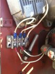
so, BR shouldn't be grounded itself (at least not to the gen), negative off of BR to gen ground. positive off of BR to one end of fuse holder, then reroute the other end of the fuse holder to TB3. in my picture, can you tell me which terminal that is? looks like maybe the top right-most since that wire has a little red ring about 1/2" away from the terminal. then disconnect the other two blue insulated leads running from the VR (top row, left two) so i can remove the VR body? what about the caps? definately one just below (visible in pic tilted about 45 degrees) and maybe another one on top (red covered cylinder).

apologies for my ignorance, but i'd really like to not make the situation worse...

ahm
 

Keith_J

Well-known member
3,657
1,316
113
Location
Schertz TX
For that photodiode work-around, a small LED, powered off the output of the bridge rectifier with a 500 ohm resistor or so in series to reduce the current will trick it. This way, the batteries won't be discharged when the generator isn't running.

The bridge rectifier should be isolated as packaged. Yes, the red labeled wire off the existing regulator is the output. Although I would fuse the regulator's output to protect it. The stator is robust

The capacitor on the terminal board can stay. The one on the regulator isn't needed.
 

amolaver

Member
64
6
8
Location
maryland
gotcha - thanks for the help! now just waiting for the dang BR to show up. should get the stock VR and its bits out of the way tomorrow. will update when progress is made or other silly question needs answering :) really - thanks!

ahm
 

crazymechanic

New member
24
0
0
Location
MD
wiring

Hi Im having same problem , I installed new stator same low a/c coming out of the 2 wires , changed magnet Baboom over 40 volts A/C , then connected regulator and melt down in the stator (fried it ) your wiring on the reg is different then mine look at picture , either I have a bad reg or I have wrong wiring either way new stator on way but look at my wiring on the reg ? does any one have proper schematic of wiring ?>
 

Attachments

Last edited:
Top
AdBlock Detected

We get it, advertisements are annoying!

Sure, ad-blocking software does a great job at blocking ads, but it also blocks useful features of our website like our supporting vendors. Their ads help keep Steel Soldiers going. Please consider disabling your ad blockers for the site. Thanks!

I've Disabled AdBlock
No Thanks