• Steel Soldiers now has a few new forums, read more about it at: New Munitions Forums!

  • Microsoft MSN, Live, Hotmail, Outlook email users may not be receiving emails. We are working to resolve this issue. Please add support@steelsoldiers.com to your trusted contacts.

New light-off of an MEP004A--engine good, not sure about electrical side

1800 Diesel

Member
768
26
18
Location
Santa Rosa County, FL
Was able to fire up an MEP4 (ASK model) this evening. (Sorry no photos yet...late night & have to travel a few days this week).... Here's the basic report:

Engine was found with oil & filter & full coolant & both fuel filters. Filled tank with my standard mix of
TC3 O/B oil, fuel additive & diesel & then primed the fuel system & had the unit running in short order. No fault indicators, good frequency, oil pressure DC charging good. A couple issues showed up on the gauge board as follows:

1. AC voltmeter is "stuck" on 120, regardless of the selector switch setting.
2. Courtesy outlet functions properly (ran a 1500 watt heater but did not measure voltage).
3. Main circuit breaker switch seems to not function (no amber indicator light up when pushed up)..
4. With the main circuit breaker pushed up (closed position) I get ~240v at each of the three output lugs.

It seems the generator is working OK but I need to sort out the voltmeter or selector switch malfunction. Any ideas anyone?

Thanks,

Kevin
 

sewerzuk

Member
524
12
18
Location
Seaside, OR
1. Not all that uncommon to see bad meters, but I would verify it is bad by attaching a DVOM to the meter to make sure it is receiving a proper input.
2. Good! At least you're sure the set is generating power.
3/4. If you are getting voltage at the output terminals, then the breaker is closing...just not remaining closed. Here is how I would begin troubleshooting this:

1. Start up the generator.
2. Test/reset all of the warning lights. Make sure all of the light up during test, and all go out when reset.
3. Check the amber contactor light by pushing in on it.
4. Use a DVOM to verify proper voltage AND frequency on both the convenience receptacle and all 3 output lugs (both phase to phase and phase to neutral). If your set has an undervoltage, overvoltage, or underfrequency condition the breaker will not close.
5. Attempt to close the contactor with the battleshort switch in battleshort (bypasses some of the safety trips).
6. Break out the schematic on page 345 the -12TM. Find S-6 (contactor switch). Trace the circuit path through each of the safety contacts (K11, K12, K13, etc.). Use a DVOM to check for 24v at points in this circuit path (24v will only be present when you hold the contactor switch in close).
 

1800 Diesel

Member
768
26
18
Location
Santa Rosa County, FL
1. Not all that uncommon to see bad meters, but I would verify it is bad by attaching a DVOM to the meter to make sure it is receiving a proper input.
2. Good! At least you're sure the set is generating power.
3/4. If you are getting voltage at the output terminals, then the breaker is closing...just not remaining closed. Here is how I would begin troubleshooting this:

1. Start up the generator.
2. Test/reset all of the warning lights. Make sure all of the light up during test, and all go out when reset.
3. Check the amber contactor light by pushing in on it.
4. Use a DVOM to verify proper voltage AND frequency on both the convenience receptacle and all 3 output lugs (both phase to phase and phase to neutral). If your set has an undervoltage, overvoltage, or underfrequency condition the breaker will not close.
5. Attempt to close the contactor with the battleshort switch in battleshort (bypasses some of the safety trips).
6. Break out the schematic on page 345 the -12TM. Find S-6 (contactor switch). Trace the circuit path through each of the safety contacts (K11, K12, K13, etc.). Use a DVOM to check for 24v at points in this circuit path (24v will only be present when you hold the contactor switch in close).
Sewerzuk--Thanks for the quick reply. I'll return home on Thursday to run through your steps and will also study safety contact details in the TM this evening.

A few other details--when I closed the main breaker last night I believe it stayed closed....though no bulb indication at all (hoping just a bad bulb). The output lugs remain hot after several minutes of running.

I did find two bad red indicator bulbs. Robbed two from an adjacent unit to clear that problem. I reset the panel switch twice and no faults were indicated, but will follow your specifics when I return home.
 

1800 Diesel

Member
768
26
18
Location
Santa Rosa County, FL
1. Not all that uncommon to see bad meters, but I would verify it is bad by attaching a DVOM to the meter to make sure it is receiving a proper input.
2. Good! At least you're sure the set is generating power.
3/4. If you are getting voltage at the output terminals, then the breaker is closing...just not remaining closed. Here is how I would begin troubleshooting this:

1. Start up the generator.
2. Test/reset all of the warning lights. Make sure all of the light up during test, and all go out when reset.
3. Check the amber contactor light by pushing in on it.
4. Use a DVOM to verify proper voltage AND frequency on both the convenience receptacle and all 3 output lugs (both phase to phase and phase to neutral). If your set has an undervoltage, overvoltage, or underfrequency condition the breaker will not close.
5. Attempt to close the contactor with the battleshort switch in battleshort (bypasses some of the safety trips).
6. Break out the schematic on page 345 the -12TM. Find S-6 (contactor switch). Trace the circuit path through each of the safety contacts (K11, K12, K13, etc.). Use a DVOM to check for 24v at points in this circuit path (24v will only be present when you hold the contactor switch in close).
Update on this unit:

Ran unit again last night and closed main circuit breaker switch. Adjusted voltage output where readings on L1, L2 & L3 (each to L0) were about 240v. Also verified frequency at 60.5 hz, which pretty much matched the panel meter. Also, the voltage selector switch decided to start working--or the gauge started reading various voltages when the switch to moved to different positions. (This morning I noticed the AC voltage gauge is stuck on about 200 volts, so I'm pretty sure the gauge itself is the problem. Have not checked input leads to the gauge yet with a DVOM. Will do that today.

Looking further into the (amber) circuit breaker indicator light & the (red) battle short indicator light, both are heavily corroded and need to be replaced. I can push in the bare bulb (with the lens unscrewed) on the circuit breaker light and it will light up; the battle short light won't do anything, but I will check for 24v on it today. Either way, both assemblies need to be replaced. Looking at the wiring going into these light, they appear to be hard-wired. Has anyone changed these out? Does anyone have some spares for either one of these? Should I solder the replacement light wires or just use crimp barrel connectors?

A few other questions:

The ASK enclosure on this units is heavily rusted. I have to decide if it's worth it to attempt to remove all panels & perform major rust repairs (including cutting out pieces and welding in new sections of angle-iron and maybe some flat panels. If the enclosure is too far gone, then it appears I will need replacement doors in order to return this unit to a "none-ASK" configuration. Is there anything else I will need besides the side & end doors? Maybe also the top panels as well? This is my first ASK model, so still don't know enough about how they're made.

Last question--this one related to a post I noticed on the other site (similar to this one)...there was a guy in NJ attempting to hook up his MEP004A (still in original 3-phase config) to his house in preparation for the incoming storm. He was talking about hooking two legs to his house panel and it seems like a few people agreed with him...(though he was heavily discouraged from hooking through a dryer outlet for safety reasons). My question is since our standard house wiring needs two 120v lines coming in (plus the neutral), how could he hook up an MEP004A with at least 208v on any of the leads coming from the generator? Maybe I missed something or still have much to learn about how the output voltages can be switched to lower voltages. If someone can explain or point me to the relevant TM section, please do. As I intend to reconfigure all MEP004As to single phase (thanks to sewerzuk :) ), the question above is more for my curiosity & general understanding of how people are able to tap off 2 of the legs to get a lower amount of power off the originally configured unit and are able to pull off 2 separate 120v leads.
 

Triple Jim

Well-known member
1,376
293
83
Location
North Carolina
As I understand it, the MEP-004A can be configured for 120/208 3 phase operation. When it is, each leg is 120V to neutral, and it's 208V between legs. If you connect two legs to your two 120V house inputs, and neutral to your house neutral, you'll have 120V at all your 120V outlets, and 208 on your 240V outlets. The 208 is not a problem for things like ranges water heaters, and usually not a problem for motors, although it would be wise to check the motor's data plate. You won't be able to get full power from the generator, but you can get most of it.
 

sewerzuk

Member
524
12
18
Location
Seaside, OR
Last question--this one related to a post I noticed on the other site (similar to this one)...there was a guy in NJ attempting to hook up his MEP004A (still in original 3-phase config) to his house in preparation for the incoming storm. He was talking about hooking two legs to his house panel and it seems like a few people agreed with him...(though he was heavily discouraged from hooking through a dryer outlet for safety reasons). My question is since our standard house wiring needs two 120v lines coming in (plus the neutral), how could he hook up an MEP004A with at least 208v on any of the leads coming from the generator? Maybe I missed something or still have much to learn about how the output voltages can be switched to lower voltages. If someone can explain or point me to the relevant TM section, please do. As I intend to reconfigure all MEP004As to single phase (thanks to sewerzuk :) ), the question above is more for my curiosity & general understanding of how people are able to tap off 2 of the legs to get a lower amount of power off the originally configured unit and are able to pull off 2 separate 120v leads.
When configured for 120/208 three phase, the generator will be producing 120v line to neutral, and 208v line to line. You can just wire up the neutral and two of the lines (any two; it doesn't matter) to your single phase house, and it will work fine (in most cases). Since your 240v loads will be seeing 208v, the will not be as efficient (motors will draw more current, resistance loads like heating elements will not produce as much heat, etc.). Resistance loads are fine with this; things like a clothes dryer, range, oven, hot water heater, etc. will have no problem with it. Electric motors are often rated for 208v-240v, but not all of them are. You should check things like your A/C unit (if you have one), well pump, and any other 240v motors you might have to make sure they are rated for 208v. If not, they STILL will work but extended use at 208v may shorten their life.
When pulling 208 single phase, you'll only be able to get about 60% of the generator's rated capacity.
Another option, if you have two separate services or breaker panels, is to supply each panel with 2 legs from the generator. If you balance your loads well, you can get 100% of the generator's capacity this way...but it may be difficult to reduce the loads on the "shared" leg enough to prevent it from tripping first. I actually ran this way for a while; 2 legs supplying the service in my shop, and 2 legs supplying the service in my house.
If you intend to use the generator as a backup to a single phase home/shop and don't anticipate needing 3 phase, then you are much better off converting it to single phase.
 

1800 Diesel

Member
768
26
18
Location
Santa Rosa County, FL
When configured for 120/208 three phase, the generator will be producing 120v line to neutral, and 208v line to line. You can just wire up the neutral and two of the lines (any two; it doesn't matter) to your single phase house, and it will work fine (in most cases). Since your 240v loads will be seeing 208v, the will not be as efficient (motors will draw more current, resistance loads like heating elements will not produce as much heat, etc.). Resistance loads are fine with this; things like a clothes dryer, range, oven, hot water heater, etc. will have no problem with it. Electric motors are often rated for 208v-240v, but not all of them are. You should check things like your A/C unit (if you have one), well pump, and any other 240v motors you might have to make sure they are rated for 208v. If not, they STILL will work but extended use at 208v may shorten their life.
When pulling 208 single phase, you'll only be able to get about 60% of the generator's rated capacity.
Another option, if you have two separate services or breaker panels, is to supply each panel with 2 legs from the generator. If you balance your loads well, you can get 100% of the generator's capacity this way...but it may be difficult to reduce the loads on the "shared" leg enough to prevent it from tripping first. I actually ran this way for a while; 2 legs supplying the service in my shop, and 2 legs supplying the service in my house.
If you intend to use the generator as a backup to a single phase home/shop and don't anticipate needing 3 phase, then you are much better off converting it to single phase.
I remember you had set up one of yours to share your shop & house loads when the generator was still set up for 3-phase. I will definitely be doing the single phase reconfigure on every one I get in. Again--was just curious about how the fellow in NJ was getting the two 120 legs to wire to his house. I knew the generator produced 120/208v but didn't know exactly how to reconfigure to make that happen. Is this a reconnection board change? I assume the voltage selector switch is only to show leg-to-leg (or to neutral) voltages on the AC voltmeter but this has no effect on the output terminals, so that leaves only a reconnection board wiring change or not?? Again, don't plan to do it that way, just trying to understand the process.

This discussion also steers me into another concern about doing the single phase reconfigure via the reconnection board changes and the required instrument wire changes. Since you've seen many more MEP4, 5 & 6 generators than me, I was wondering about the chances of getting a generator in where reconnection board wiring changes had already been performed, thus affecting the specific wiring changes required for the single phase conversion...is this a possibility or not likely? Maybe a better question--is there any such wiring reconfiguration that could have been done in the field that would cause a problem for anyone doing the single phase conversion? Or are my concerns without merit?
 

1800 Diesel

Member
768
26
18
Location
Santa Rosa County, FL
As I understand it, the MEP-004A can be configured for 120/208 3 phase operation. When it is, each leg is 120V to neutral, and it's 208V between legs. If you connect two legs to your two 120V house inputs, and neutral to your house neutral, you'll have 120V at all your 120V outlets, and 208 on your 240V outlets. The 208 is not a problem for things like ranges water heaters, and usually not a problem for motors, although it would be wise to check the motor's data plate. You won't be able to get full power from the generator, but you can get most of it.
Thanks Triple Jim--I asked sewerzuk about this--still trying to figure out if this requires changes via the reconnection board or some other method...also asked if these types of wiring changes would affect the specific wiring changes required for the single phase conversion...standing by for that info....

I still intend to "single-phase" every MEP 4 I get in, but would like to better understand the "stock" 3-phase setup and how to pull the 120 legs in case I ever need to do this in a pinch...
 

sewerzuk

Member
524
12
18
Location
Seaside, OR
I remember you had set up one of yours to share your shop & house loads when the generator was still set up for 3-phase. I will definitely be doing the single phase reconfigure on every one I get in. Again--was just curious about how the fellow in NJ was getting the two 120 legs to wire to his house. I knew the generator produced 120/208v but didn't know exactly how to reconfigure to make that happen. Is this a reconnection board change? I assume the voltage selector switch is only to show leg-to-leg (or to neutral) voltages on the AC voltmeter but this has no effect on the output terminals, so that leaves only a reconnection board wiring change or not?? Again, don't plan to do it that way, just trying to understand the process.

This discussion also steers me into another concern about doing the single phase reconfigure via the reconnection board changes and the required instrument wire changes. Since you've seen many more MEP4, 5 & 6 generators than me, I was wondering about the chances of getting a generator in where reconnection board wiring changes had already been performed, thus affecting the specific wiring changes required for the single phase conversion...is this a possibility or not likely? Maybe a better question--is there any such wiring reconfiguration that could have been done in the field that would cause a problem for anyone doing the single phase conversion? Or are my concerns without merit?
120/208 and 240/416 are the only "standard" voltages that the -004 comes configured with. So, as long as the 120/208v arrows line up on the reconnection board, the set is already running 120/208 and no changes are necessary to pull single phase 120/208. All that you would do is wire up your hot legs to L1 and L2 terminals, and the neutral to L0...bingo! Single phase 120/208.
edit: I think I understand where you are confused...you are thinking that the set must be modified in some way to get single phase 120/208 out of it. No modification is necessary...it is all in how you wire up the cable going to your house. Therefore, pulling single phase 120/208 would have no effect on a future change to 120/240 single phase.

I have never seen an MEP configured for anything other than 120/208. The military generally frowns on modifications not covered in tech manuals...the biggest modification I have seen is a fire extinguisher bolted to the side panel. It would be more likely to find a modified one from a private party sale, but I have looked at several of those over the last few years as well, and the only modification I ever saw was a civvy voltage regulator inside of an -002a. It is a pretty safe bet that, if you purchased your set at a GL auction, that it is unmodified.
 
Last edited:

1800 Diesel

Member
768
26
18
Location
Santa Rosa County, FL
120/208 and 240/416 are the only "standard" voltages that the -004 comes configured with. So, as long as the 120/208v arrows line up on the reconnection board, the set is already running 120/208 and no changes are necessary to pull single phase 120/208. All that you would do is wire up your hot legs to L1 and L2 terminals, and the neutral to L0...bingo! Single phase 120/208.
edit: I think I understand where you are confused...you are thinking that the set must be modified in some way to get single phase 120/208 out of it. No modification is necessary...it is all in how you wire up the cable going to your house. Therefore, pulling single phase 120/208 would have no effect on a future change to 120/240 single phase.

I have never seen an MEP configured for anything other than 120/208. The military generally frowns on modifications not covered in tech manuals...the biggest modification I have seen is a fire extinguisher bolted to the side panel. It would be more likely to find a modified one from a private party sale, but I have looked at several of those over the last few years as well, and the only modification I ever saw was a civvy voltage regulator inside of an -002a. It is a pretty safe bet that, if you purchased your set at a GL auction, that it is unmodified.
I believe my confusion is probably due to the readings I pulled from the ASK model MEP4 last night as follows: (all at 60 hz, meter Ectech MA220)

L0-L1 241
L0-L2 242
L0-L3 238

L1-L2 417
L2-L3 419
L1-L3 412

Should I be seeing 120 from neutral to any of the 3 legs? If so, what's causing the voltages to be showing ~ 240 in lieu of 120? I'm not familiar with your reference to the 120/208v arrows lining up on the recon board--that part I need to study in the TM. And yes this is a USN unit received via GL.
 
Last edited:

Triple Jim

Well-known member
1,376
293
83
Location
North Carolina
It appears that your generator is configured for 240/416, since within a small tolerance, that's what you're getting. It needs to be reconfigured for 120/208, but sewerzuk or someone else who has experience with that unit will have to explain. After that, you'll be getting 120 from each leg to neutral and 208 leg to leg.
 

1800 Diesel

Member
768
26
18
Location
Santa Rosa County, FL
It appears that your generator is configured for 240/416, since within a small tolerance, that's what you're getting. It needs to be reconfigured for 120/208, but sewerzuk or someone else who has experience with that unit will have to explain. After that, you'll be getting 120 from each leg to neutral and 208 leg to leg.
Agree--that's what I'm thinking too...I need to take a good look at the recon board wiring arrangement and also study the applicable TM sections...as I mentioned to sewerzuk, I didn't understand his mention of the "arrows lining up"...don't remember seeing anything like that when I recently reconfigured my 1st MEP4 to single phase using sewerzuk's low zig-zag (I think that's what he called it??) arrangement...but then I wasn't looking for anything like that...was just doing the specific wiring changes as per his instructions.... :)
 

212sparky

Well-known member
1,822
38
48
Location
Monroe/ Ohio
It is easy to reset the voltage by undoing the 12 nuts on the reconnection board, line up the arrows redo the nuts and your done. Also read the TM
 

sewerzuk

Member
524
12
18
Location
Seaside, OR
Agree--that's what I'm thinking too...I need to take a good look at the recon board wiring arrangement and also study the applicable TM sections...as I mentioned to sewerzuk, I didn't understand his mention of the "arrows lining up"...don't remember seeing anything like that when I recently reconfigured my 1st MEP4 to single phase using sewerzuk's low zig-zag (I think that's what he called it??) arrangement...but then I wasn't looking for anything like that...was just doing the specific wiring changes as per his instructions.... :)
The movable part of the voltage reconnection board should have an arrow on it. That arrow should line up with one of two voltage readings on the fixed part of the board. As triplejim stated, your set is likely configured for 240/416 right now. To change voltage, you just remove the nuts on the board, remove it, and reinstall it with the arrow pointing toward the 120/208 voltage.
Some boards don't have the arrow on them...but all the ones I have seen have some kind of mark.
 

1800 Diesel

Member
768
26
18
Location
Santa Rosa County, FL
The movable part of the voltage reconnection board should have an arrow on it. That arrow should line up with one of two voltage readings on the fixed part of the board. As triplejim stated, your set is likely configured for 240/416 right now. To change voltage, you just remove the nuts on the board, remove it, and reinstall it with the arrow pointing toward the 120/208 voltage.
Some boards don't have the arrow on them...but all the ones I have seen have some kind of mark.
Finally got a chance to dig into the TM--found a good description of the recon board and figure 2-7.....also visually confirmed the position of the board on the ASK model I'm working....The arrows do indeed line up in the 240/416 position and connection studs 1, 2 & 3 are exposed or not covered by the board. Looking back at figure 2-7, it seems to me that the right-hand part of the illustration (showing the 240/416 board position) is in error as it shows the board in the correct position but shows the arrows lined up at the 120/208 position..also the two arrow positions on the lower board are incorrectly shown on the right side figure. The left side figure shows the arrow positions correctly with the 120/208 arrow being the lower of the two sets....do you agree? Edit--the TM I looked at was "ARMY TM 9-6115-464-12".

Lesson learned--before I do any work on these sets, I'll verify the recon board position. Thanks to all for the assistance. :)
 
Last edited:

1800 Diesel

Member
768
26
18
Location
Santa Rosa County, FL
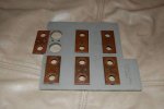
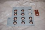
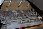
Copper plate rivets removed (with photos)

It is easy to reset the voltage by undoing the 12 nuts on the reconnection board, line up the arrows redo the nuts and your done. Also read the TM
Setting up this morning to reset the recon board for 120/208v (and then to do the single phase mod), when I removed the board, found the copper plate that connects #6 & #12 lug was loose as seen in photo #2. Don't know if it slipped off of #6 when I pulled the board up or not....have to assume this is what happened. The heads of the rivets are missing from the upper side, so it appears they were drilled out...just can't figure out why....maybe someone will weigh in if they've come across this....I plan to put it back in place across #6 & # 12 lugs....

Edit--first photo file name incorrectly calls out voltage as "208-416"...meant to write "240-416"....
 

Attachments

Last edited:

1800 Diesel

Member
768
26
18
Location
Santa Rosa County, FL
The movable part of the voltage reconnection board should have an arrow on it. That arrow should line up with one of two voltage readings on the fixed part of the board. As triplejim stated, your set is likely configured for 240/416 right now. To change voltage, you just remove the nuts on the board, remove it, and reinstall it with the arrow pointing toward the 120/208 voltage.
Some boards don't have the arrow on them...but all the ones I have seen have some kind of mark.
If you get a chance this evening, please take a look at my post #16--photos of the recon board work and conditions found....thanks,

Kevin

Update--completed the 120/208 shift and also completed the single phase conversion this evening....too late around here to light it off though...won't be able to do that 'til the end of the week. Hopefully I switched all the wiring correctly... :)
 
Last edited:
Top
AdBlock Detected

We get it, advertisements are annoying!

Sure, ad-blocking software does a great job at blocking ads, but it also blocks useful features of our website like our supporting vendors. Their ads help keep Steel Soldiers going. Please consider disabling your ad blockers for the site. Thanks!

I've Disabled AdBlock
No Thanks