• Steel Soldiers now has a few new forums, read more about it at: New Munitions Forums!

  • Microsoft MSN, Live, Hotmail, Outlook email users may not be receiving emails. We are working to resolve this issue. Please add support@steelsoldiers.com to your trusted contacts.

M35a2 Wiring Harness Trouble

Hello Guys,

I am installing a wiring harness in my m35a2, I'm having trouble finding the correct path and the places of attachment into the truck, could someone send me some pictures of the engine area showing the way that the electrical wiring does and its anchorage points ? I installing only the front wiring.
Since my truck had no wiring harness I could not remove the old wiring to install the new at the same place.

I appreciate if you can help.

Best Regards
 

Warthog

Moderator
Super Moderator
Steel Soldiers Supporter
13,774
232
63
Location
OKC, OK
While it doesn't show exact placement, the diagram from the TM 9-2320-209-34P parts manual will give you the general idea. It should be figure #67 for the multifuel.

You will need to use your imagination to "see" the truck parts (firewall, fenders, engine, etc)
 

bigboy44

Member
409
2
18
Location
Ava, MO.
All the clamps were left on the harness and if I remember right the big group of wires went into a hole near the steering column along with the wiring to the instrument panel. Guess I should have taken pictures! Good Luck Filipe
 

M35A2-AZ

Well-known member
Steel Soldiers Supporter
3,222
392
83
Location
Tonopah, AZ
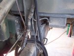
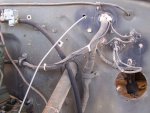
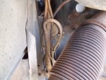
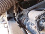
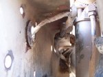
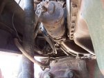
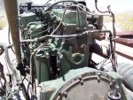
Not sure if these will help but here is some pics from a deuce I am restoring.
I used the pic to replace the harness .
Sorry this is all I have.
 

Attachments

silverstate55

Unemployable
2,075
872
113
Location
UT
I'm in the process of replacing the front wiring harness, and I took notes (and drew pics, but only I can interpret my chicken-scratching :-D).

Start with the first photo posted by M35A2-AZ above: where the wiring harness goes into the cab, find the cab-related portion and feed it through the hole in the firewall. Hopefully you have the 2-piece metal grommet held in by 2 bolts that goes around the wiring harness cab entry point; if not, it would be a good idea to find one from either a NOS seller or someone parting out a Deuce, as the edges are rounded & prevent cutting/chafing for the wiring harness.

The cab-interior portion will have the 3-lever light switch plug along with the turn signal switch plug on it, and plug ends #40, #1, #17, #11 (two of these), #27, #28, #33, #36, among others, and TWO 2-pin plugs (front drive axle indicator & starter switch).

You'll know that end when you start laying out the entire harness.

I'll split this into separate posts so that I don't get logged out & you don't get overwhelmed.
 
Last edited:

silverstate55

Unemployable
2,075
872
113
Location
UT
Inside the cab, run the strand that has wire plugs #40, 17, 27, 28, 33, 36, and the two 2-pin plugs on top of the metal cab brace that resides above the steering column; these will go to the gauge cluster & other switches, as delineated below.

#85: Low air pressure buzzer
#27A, 27A: Front drive axle switch (2-pin plug on the side, single plug on the rear of switch)
2-pin plug: starter switch (I forgot to write the number down, it was pretty obvious though)
#17: High-Beam indicator
#40 (2 of these): Dash light indicators
#27: This connects to the 5-wire "spider" loom, it provides backlighting for gauges
#28: Fuel gauge
#33: Coolant/Engine Temperature
#36: Oil Pressure
 

silverstate55

Unemployable
2,075
872
113
Location
UT
Now let's finish connecting everything inside the cab, all that's left should be on the left side of the steering column.

Accessory Switch: I installed a new switch, and it's nice to have a positive locking engagement when turning this switch off & on, instead of having it loosely flop around. Remove this switch, and keep the locating tab at the top of your orientation. Look at the back of the switch, at the 4 plug mounts. With the locating tab facing up, and looking at the rear of the switch, plug in the following: #11 Top Left & #11 Bottom Left; #27 Top Right; #1 Bottom Right. Reinstall this switch with the locating tab UP (goes into the hole in the dash, kind of obvious).

#55 (2 of them): Manifold Heater Switch

Connect the turn signal plug assembly to the turn signal switch housing on the steering column.

Connect the large plug assembly to the 3-lever light switch. NOTE: the 3-lever light switch housing is removed from the back of the dash, so you can either install the plug assembly into the mounted 3-lever light switch housing as it's mounted, or remove it to install the plug assembly, then figure out a way to weave it back into place into the dash. You must first remove the 3 levers from the front of the switch housing before you remove the housing from the dash.
 

silverstate55

Unemployable
2,075
872
113
Location
UT
Now we can start tracking the installation of the harness outside of the cab. On the firewall, find plugs #25 & #10; plug these into one of the circuit breakers mounted on the cab firewall (see the first photo posted by M35A2-AZ above).

**NOTE: My truck only had one circuit breaker, the other one had been removed along with the entire cab heater & blower assembly. If someone knows what other 2 wires go into the other circuit breaker, please feel free to post it below. I have 2 wires leftover that go into the missing circuit breaker, but I didn't write their numbers down as I don't have a heater nor blower assembly.** MY APOLOGIES.

The harness splits into 2 branches here on the firewall, the one with the larger-guage wires with red heat-shrink (and the horn wires, two #25 plugs) goes along the firewall behind the engine, and drops down to the frame rail there. The other branch will drop down to the driver's side frame rail, but just before it does 2 additional branches come off of this harness branch. This should be a metal plug assembly for the turn signal flasher unit (I relocated mine to the firewall) and a ground wire, and a set of 3 plugs for the headlights Hi-Beam switch (mounted to cab floor).

Refer to the second photo posted by M35A2-AZ above: the Hi-Beam plugs will go into the floor-mounted switch, and you'll have to crawl under the truck and rest up against the back of the front tire to see this. The Hi-Beam switch has the plugs arranged in an "L"-shape, the very top plug is #18, the bottom plug (closest towards the front of the truck) is #17, and the bottom plug closer to the rear of the truck is #16.

Now route the rest of this driver's side branch harness along the inside of the frame rail to the bottom of the radiator. Plug #19 will go to the Blackout Drive Light (plug in the middle of the back of the housing; the plug at the bottom is a ground wire). Looking at the back of the headlight housing on the driver's side, plug #18 will go onto the top left plug on the housing (at the 10 o'clock positon), plug #17 goes on the top right housing plug (2 o'clock position), and the bottom plug on the housing (6 o'clock position) is a ground. Ground the headlight & BO drive light to the frame rail.

Plug #25 should connect with the horn wire coming out of the steering box.

Now route the turn signal wires through the grommet hole in the frame below the radiator, and through the fender support bracket up to the box mounted inside the front of the driver's side fender (bolts/nuts that hold this box to the fender also mount the turn signal bracket to the fender). Remove the bolts/nuts holding this box to the inside of the fender, and connect the appropriate wires to the turn signal & BO lights here (#460 Left Turn Signal, #491 Parking Lights, #20 BO). Reinstall the 4 bolts/nuts holding the box & turn signal bracket to the fender.
 

silverstate55

Unemployable
2,075
872
113
Location
UT
Get underneath your truck, and you should see a branch still dangling down that has a couple of plugs and a large metal connector assembly. The two #75 plugs should go to your brake light switch on your Airpack, and you'll need to thread the large metal plug through the crossmembers to connect with the rear wiring harness metal connector assembly on the inside frame rail behind the Airpack.

Moving to the passenger's side of the motor, this harness branch should be dangling inside the frame rail by the starter. However, you should have a small branch with 2 plugs that go along the top of the passenger side of the engine: #55 goes to your manifold flame heater, and #33 should go into a plug near the thermostat for your engine coolant temperature sending unit.

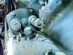
Now let's connect the wires near the starter & starter relay. Refer to the third photo by M35A2-AZ above: in the middle of the photo, behind the wires you can just barely see a cylindrical object mounted to the rear of the engine block...this is the oil pressure sending unit; connect plug #36 to this sending unit.

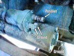
In the fourth photo above, just out of view of the pic to the upper right is the starter relay, mounted to the engine block. On top of the relay you should have 2 small-diameter stud bosses with nuts and/or lock washers. Wire #743 (or 74R per the schematic) attaches to the stud boss closest to you (the stud boss farthest from engine block; the inside stud boss closest to engine block isn't used).

On the bottom of the relay, you've got 2 large stud bosses with lock washers & 3/4" nuts. The inside stud boss on the bottom of the relay (the one closest to the engine block) is a ground; use an 8-gauge or larger cable and ground this to the ground post on the starter solenoid closest to the engine block (more on this later). The relay's bottom stud boss closest to you (furthest from engine block) will mount Wire #10 from the harness and an 8-gauge or larger cable that will connect with the top positive post on the starter solenoid (more on this later).
 
Last edited:

silverstate55

Unemployable
2,075
872
113
Location
UT
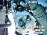
Now on my Deuce, my starter solenoid might differ from yours. The starter solenoid resides on top of the starter itself, they are bolted together. Look at the front of the solenoid: mine has 3 large stud bosses, 2 facing forward (horizontal) & one that is in the middle facing vertical...looking at my photo #3, I have labeled these for their functions. The 2 small metal tab grounds with small machine screws in them are for ground cables.

So we have what appears to be 2 large stud bosses and 2 small metal tabs that are grounds, and one large stud boss that is a positive cable attachment point. Connect wire #2 (alternator charge wire, should be next to the oil pressure plug #36 and a couple of other wires) to the POSITIVE stud boss on the solenoid, along with the 8-gauge or larger cable from the POSITIVE stud boss on the starter relay (the stud boss on the bottom of the relay, that is closest to you & also connects wire #10). Don't tighten these down yet, as this stud boss will also connect with the battery cable from the batteries (1/0-gauge or larger; DO NOT CONNECT UNTIL THE ENTIRE HARNESS IS INSTALLED).

Now we can connect the 8-gauge or larger ground cable from the bottom stud boss on the starter relay above (the stud boss furthest from you on the bottom of the relay, closest to the engine block) to the inside small ground tab on the solenoid, just below the solenoid's POSITIVE stud boss (refer to my photos #2 & #3 below).

Make up a ground wire to connect from the outside small ground tab on the solenoid (the small tab with the machine screw on the left side of photos #2 & #3 below, under the large stud boss ground) and connect to the main grounding large stud boss on the front of the starter itself (and connect this stud boss with a 1/0-guage or larger grounding cable, and ground to inside frame rail). On my Deuce, the wire was a small 14-gauge wire; I will replace this with a much larger cable (probably 8-gauge or larger as I have plenty of it...the bigger the better when it comes to wiring).

20130908_Deuce-Starter_01_800px.jpg 20130908_Deuce-Starter_01a_800px.jpg 20130908_Deuce-Starter_01b_800px.jpg
 
Last edited:

silverstate55

Unemployable
2,075
872
113
Location
UT
Connect the other Plug #2 to the positive voltage output on your alternator, and plug #1 to the alternator switch wire (if you still use the stock Deuce alternator). On the passenger-side headlight, while looking at the back of the headlight housing, plug #17 will mount to the top left connector (10 o'clock position), the #18 wire will mount to the top right connector (2 o'clock position), and the bottom connector is a ground (ground to frame rail). Both #25 plugs will go into the horn solenoid switch.

Now route the final branch of the harness through the grommet hole in the frame rail below the radiator (as shown in Photo 6 above), through the fender support bracket, and to the box inside the fender for the turn signal lights (#460 Right Turn, #491 Parking Lights, #20 BO) just as you did on the driver's side.

Once all the branches & plugs are in place, you can start connecting the wire clamps. Don't install these until your entire harness is done, otherwise you might have to remove the clamps to shift the harness around for clearance.

As a final step, connect your battery cable (the one coming from the batteries) to the top (positive) post on the starter solenoid, and connect the battery cable to the batteries.
 
Last edited:

silverstate55

Unemployable
2,075
872
113
Location
UT
I made some errors in my previous posting #10; these have been corrected. I also posted some photos from my Crackberry phone of the starter & solenoid to explain where all the wires go.
 

olly69

Member
78
1
8
Location
Cuba, New York
Signal switch harness

If I've missed anything or am incorrect, please let me know. Hope this helps.
I have been having a problem with my signals - sometimes they work, most time they don't. The wires are in bad shape coming thru the firewall to the switch. One was totally bare of insulation. I tried to tape over the bare wires, but it didn't help. Is there any way of fixing just that section of the harness? Can just the plug be rewired? Thanks!
I am going to look at the pictures & description you did to see if it helps me. Thanks for all the work you did to post it!
 
Last edited:

706james815

Member
28
1
8
Location
Brunswick, Georgia
M35a2 wiring

I have a issue somebody decided to cut the connector on my light switch. The main power switch and turn signals . I have the ends but some of the little tags are gone help!!!!

1970 M35a2 Kaiser:(
 
Last edited:

706james815

Member
28
1
8
Location
Brunswick, Georgia
Lord have Mercy! I have my work cut out for me . Is there maybe numbers on the wire them selves? Some of the tags are missing too. guess I'll have to cut the whole harness open to follow them out. Will post some pictures in the morning
 
Top
AdBlock Detected

We get it, advertisements are annoying!

Sure, ad-blocking software does a great job at blocking ads, but it also blocks useful features of our website like our supporting vendors. Their ads help keep Steel Soldiers going. Please consider disabling your ad blockers for the site. Thanks!

I've Disabled AdBlock
No Thanks