• Steel Soldiers now has a few new forums, read more about it at: New Munitions Forums!

  • Microsoft MSN, Live, Hotmail, Outlook email users may not be receiving emails. We are working to resolve this issue. Please add support@steelsoldiers.com to your trusted contacts.

new MEP - items of concern?

ragnar

New member
10
3
3
Location
Virginia
Hello All,


Long time reader, first time poster. Last summer I researched generators for several months (losing power in sweltering July for 5 days will make you a bit neurotic about picking the right genset...), and finallydecided the MEP was what I needed. Many of the postings on thiswebsite led me to that decision - it has always been a trove of useful information. That year I bought a greatrefurbished 002A off of Storeman, which has served me faithfullysince that time (Thanks again, Storeman). Not long thereafter Idecided I wanted to get one off of auction and try my luck at it. Iwon a 002A a few months ago from govliquidation, which seemed to be agood bet. It had 158 hours on it (the hour meter at least seems to beauthentic), it still had batteries, oil, and diesel in the tank, andthe oil filter had a 10/12 date on it. Due to competing priorities athome, it wasn't until the last few weeks when I finally got aroundto going through the post-purchase maintenance procedures (flushingall fluids, changing filters, etc). One of the most satisfying sounds in the world I have heard wasthe diesel roaring to life the first time I cranked it. I gave it astress test with a 50 amp load for 2.5 hours (the gauge read 80-85%during that run) and she barely broke a sweat. Needless to say, I wasquite happy.


Now, all that being said, I did noticesomething during my physical inspection that worried me a bit. What Iassume are the cooling fins of the engine appear to be rusted. I tooktwo pictures – one from inside the pop-open cover above the oilfilter, and the other is taken through the flip-open grates justbeneath the exhaust tube. Should I be concerned about this? Is thereanything I should do to rectify the problem?
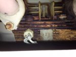
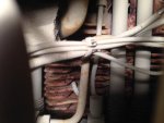
photo-1.jpgphoto-2.jpg


The other oddity I noticed was afterrunning it for several hours, the battery gauge needle was in theupper red portion of the gauge. I had never noticed my other unitdoing this, so I wasn't sure if it signaled a problem with the DCcharger? Or is that normal?


Thanks in advance for the advice.
 

gimpyrobb

dumpsterlandingfromorbit!
27,786
755
113
Location
Cincy Ohio
I agree, I wouldn't put too much concern into the rust, but if you do, Storeman and I have parts available.
 

Triple Jim

Well-known member
1,375
287
83
Location
North Carolina
If the rust is so fluffy that it blocks the air flow, you could scrape it out a bit. Mine is fairly rusty, but there's still plenty of open channel for air flow, and I don't see how I could ever load the thing to 100% steadily in backup service, so I haven't concerned myself. If it gets too bad I'll invite Jim C. over for a day or two to totally restore the thing in exchange for free beer.

Rob, I think it's a good thing that you change your avatar fairly often, but maybe now you should take a break for a year or two. Unless something better comes along, of course.
 

Isaac-1

Well-known member
1,970
50
48
Location
SW, Louisiana
I would not worry too much about the rust unless you live in a coastal area, in that case you may want to clean it up and paint it with high heat paint. As to the voltage issue sounds to me like you have a battery charging regulator going bad. You should test it with a good multimeter to make sure it is not just a bad instrumentation problem.

Ike
 

1800 Diesel

Member
768
26
18
Location
Santa Rosa County, FL
Everyone else has you covered on the rusting fins. I have an MEP-003A I purchased back around 1994 & it has the same rusting fins condition. Over it's lifetime this unit has provided standby power for our family & friends through seven hurricanes, including Katrina.

On the DC overcharging condition, before you do any work on the charging system, confirm that both of your batteries are fully charged and all cells are good. Also clean terminals on cables & clean battery posts to make for good connections (at both ends of ground & starter connection too). I recently observed the same problem with our MEP3 & discovered one of the batteries was bad. After installing two good batteries, the charging system went back into the green--putting out IIRC about 28 volts. I'm guessing if you tested voltage across the two batteries you'll find something in the 32-38 volts range.

Kevin
 
Last edited:

Ray70

Well-known member
2,595
5,912
113
Location
West greenwich/RI
You know... Tripple Jim was reading my mind... I was just about to give GimpyRobb a shout out for having some of the best avatars on here, but you beat me to it! Now leave it alone for a while so we can enjoy it! As for the rusty fins you could probably get a lot of the loose flakey rust off by passing something like a sawzall blade or a thin file back and forth between the fins a few time them blow it out with compressed air. As long as the air passages aren't blocked off too badly it will be fine.
 

Triple Jim

Well-known member
1,375
287
83
Location
North Carolina
I understand, and certainly believe you. Within limits, a good battery can regulate charging voltage when the charge current is fairly low, like in this system. It's not ideal though, because if left running long enough, the voltage will creep up and you'll start losing electrolyte from the battery.
 

ragnar

New member
10
3
3
Location
Virginia
Gents,

My apologies for not reading the sticky thread on the DC voltage regulator first...party foul on my part.

Some anecdotal background on the batteries in question: the original test run was with the batteries that were with the unit when I bought it. I had trickle charged them and voltmeter indicated they were still good. That, however, may not be the case.

So today as fate would have it I'm snowed in, so I have ample time to play with the MEP. I went through Speddmon's procedure (first with the old batteries, and then with the newer Interstate batteries I have from my other MEP), and here are the results:

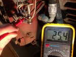
1) With the set OFF, measure DC Voltage at the regulator wire that is marked with the red band. Should be around 24 to 24.5 volts DC....Is it?

- Actually it was a little high - 25.4 (picture included to make sure I was measuring the correct lead...)

photo-3.jpg

2) Start the generator and measure the voltage across the regulator again... should be between 26 and 28 volts....is it?

- It started out at 25.4 and rose slowly but steadily. After a few minutes it was above 30v.

3) Measure the voltage across the battery terminals...

- The battery voltage followed the regulator voltage a few 10ths of a volt behind, but it steadily followed suit up past 30v.

4) Check the fuse....

- fuse is good

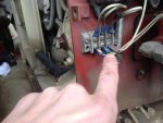
5) Measure the voltage at the two leads coming from the stator under the blower wheel....

- I got a big fat zero volts, but am including a picture so you all can check me to make sure I was measuring across the correct leads.

photo-4.jpg

All the while the voltage at the regulator and the battery terminals were climbing, the battery needle on the control panel also rose into the red.

After doing this test, I shut her down and swapped out the old batteries with ones I know are good - and had the same results. Both times I let the voltage run up to 31 volts or so before shutting it down (measured at the regulator and the battery terminals both). It was still climbing when I shut it down.

So do I have a bad stator AND a bad voltage regulator?
 

Isaac-1

Well-known member
1,970
50
48
Location
SW, Louisiana
Sounds to me like you have a bad voltage regulator, if the stator was bad you would not see voltage rise over time, so I am going to assume you were not reading it right, did you put your meter on AC volts for the stator?

Ike
 

steelypip

Active member
769
68
28
Location
Charlottesville, VA
Ike called it - almost certainly a bad DCVR.

Small items that might be useful to know:

1. battery voltage is a variable even when the battery has been resting off the charger. A resting fully charged '12V' wet cell battery might read as low as 12.2 V or as high as 13 V. Yes, that nominal two volts per cell is really more like 2.1 V/cell at full charge. Probably the best way to really understand these voltages is to measure the voltage of each of your two batteries before you hook them together. When you connect the jumper between them, you'll get the sum of the two volt readings, so 24.4-26 V is just fine for a 2x12V string.

Then you turn the gen set on, but don't start it and compare the DMM reading with the panel gauge reading. This tells you whether the panel gauge is bad or not.

2. These regulators are a very simple shunt regulator connected to a full wave bridge rectifier. The charging stator is a single coil, single phase design, as used in old motorcycles among other things. The only thing unusual about the system compared to an old motorcycle, riding mower, or whatever is that its regulated voltage should be about 28 V instead of 14 V.

3. Shunt regulators work by dumping any excess power made by the stator to ground. This means that a) the maximum stator voltage is very close to the regulated voltage b) the stator is always making as much amperage (and heat) as it possibly can, and c) the regulator gets hot dumping excess power to ground, so good heat sinking and airflow are required.

Here's a simple diagram of what's supposed to be going on in the DC charging circuit:

single-phase-regulator.jpg
(stolen from here: http://racetechelectric.com/ft-751-voltage-regulators.html)

Leftmost is the stator, then the four diodes that make up the rectifier bridge - they turn the AC from the rectifier coil into pulsating DC, then a relay-like thing which is actuated by the 'relay circuit'. The 'relay like thing' is the Silicon Controlled Rectifier (SCR) that actually gets the job of dumping excess power from the stator coil to ground once the charging voltage has risen above 29 V or so.

These charging circuits aren't very efficient, but they are cheap to make, so they're used almost everywhere. It should be doable to find or modify a cheap generic replacement somewhere if we can find one with easy access to the voltage reference part of the regulator that allows us to tweak it to regulate to 29 V instead of 14.5, or, alternately, to find something else with a 24 V magneto-stator charging system.


ragnar

New member
10
3
3
Location
Virginia
Steelypip, your posting actually made me question my setup... Because my generator's primary purpose is house backup power, I do not have it grounded - instead the cable I run from the generator to my service panel connects to my house ground bar.

That being said...in order to exercisethe generator every month or so, and to test it initially, I wired upa few outlet boxes to the generator's voltage lugs. So when I amrunning devices off of these outlets to exercise the generator (spaceheaters usually) – or more critically – during the testsmentioned in this post - the generator itself is not grounded. Doesthat mean that the DCVR is sending excess voltage into the batteriesinstead of to ground? Is that the source of my problem? Or is that just a side bar error that is unrelated?
 

Munchies

Member
417
3
18
Location
Keesler Air force base/ MS
For the dc side the set ground can be ignored. treat it like a closed loop 12 or 24v motor vehicle for the DC side of things.
BAD DC VR. Only way it can over charge is if its bad. Swap it out. Buy triple jim some beer and tell him to finish engineering a beefcake VR or the new guy with the paralleling thread has prices to repair them that seemed reasonable. Worth it to me to not have to deal with potted components.
 

steelypip

Active member
769
68
28
Location
Charlottesville, VA
As Munchies almost said, 'ground' isn't 'Ground.' In DC electrical systems, we use the term 'grounded' to refer to whatever is connected to the frame of the vehicle/machine/whatever and uses that frame as one of the conductors to the battery. Most of these DC-powered things made since about 1960 or so are 'negative ground' meaning that the negative terminal of the battery is connected directly to the frame of the machine. So on a car, or our MEPs, the wires in the DC system all carry positive voltages relative to the frame. If you think about it, a car isn't usually grounded at all because the tires are a pretty effective insulator.

Older machinery could be wired either way, as either 'negative ground' or 'positive ground.' But the system has no idea what the potential of the frame of the generator is relative to earth ground. And yes, 'earth ground' is the term to use when you want to make sure people understand what you're talking about.

You should always have the generator frame connected to SOME kind of earth ground when it's running, to protect you from being electrocuted by an AC mis-connection or fault. If you leave the frame ground bonded to the house ground all the time, that's just fine. But if you're using a four-pin twist-lock connector to connect the genset to house ground and disconnecting from the house for testing, you should have a different four-pin twistlock with a driven ground rod that you attach to, or some other way of getting that frame bonded to an earth ground.

Note that this has nothing to do with the (relatively benign) 24V DC system at all, but has everything to do with you not being electrocuted by your genset during testing.
 

ragnar

New member
10
3
3
Location
Virginia
Thanks - will do. I will drive a separate ground rod and connect to it whenever I'm testing/exercising the generator.

Thanks everyone for your input - I have a replacement DCVR on order.
 
Top
AdBlock Detected

We get it, advertisements are annoying!

Sure, ad-blocking software does a great job at blocking ads, but it also blocks useful features of our website like our supporting vendors. Their ads help keep Steel Soldiers going. Please consider disabling your ad blockers for the site. Thanks!

I've Disabled AdBlock
No Thanks