• Steel Soldiers now has a few new forums, read more about it at: New Munitions Forums!

  • Microsoft MSN, Live, Hotmail, Outlook email users may not be receiving emails. We are working to resolve this issue. Please add support@steelsoldiers.com to your trusted contacts.

Picture of your MEP terminal hook up to house?

gishooter

Member
32
1
8
Location
Ozarks
Good morning,
I'm in the process of getting my MEP-003A set up as a standby generator for the house. The sticky at the top was very helpful for educating my electrician on the particulars.
My electrician asked if I could find a picture or two of how folks here have connected the MEP terminals to the power cable that runs to the electrical service of the house. Hoping steddmon chimes in too!

Thanks!
Chris
 

rosco

Active member
Steel Soldiers Supporter
2,102
30
38
Location
Delta Junction, Alaska
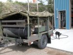
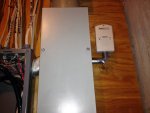
Here is mineDSCN4701.jpg If you look inside the door, you can see the Transfer switch. This is actually my shop & the power goes from here to my house - both are on one meter. I can power both (with manual load shedding), with the MEP 003. I have it fix for the "long haul" with the 100 gallon Aux tank.
 

Warthog

Moderator
Super Moderator
Steel Soldiers Supporter
13,774
232
63
Location
OKC, OK
I think he is asking for a picture of the cable hookup at the MEP itself, as in which wire to which leg. Of course I could be wrong. ;-)
 

Chrispyny

Member
294
12
18
Location
NY
hey how about how you guys are clamping down on the wires at the split lugs the box on the generators? I mentioned this in another thread some time ago but was unsure of how it was suggested.

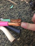
How are you guys attaching your wires to the split lugs to ensure a good bite ? .. 10 guage wire doesn't hold up well in the split lugs for me. Even clamped down hard, it still leaves a lot to be desired.
 

DieselAddict

Well-known member
Steel Soldiers Supporter
2,532
2,059
113
Location
Efland, NC
On the generator end I installed a 50a 4-wire outlet and wired it up to the generators output terminals and to the chassis ground. I mounted the box on the lower left side of the generator.

You should connect the leads it using the terminal diagram on the generator. How you connect it is based on the position of the phase selection switch on the back.

Since you are going to be connecting it to a house that has a ground system be sure to remove the bonding jumper between the neutral and the chassis ground on the generator.
 

DieselAddict

Well-known member
Steel Soldiers Supporter
2,532
2,059
113
Location
Efland, NC
hey how about how you guys are clamping down on the wires at the split lugs the box on the generators? I mentioned this in another thread some time ago but was unsure of how it was suggested.

How are you guys attaching your wires to the split lugs to ensure a good bite ? .. 10 guage wire doesn't hold up well in the split lugs for me. Even clamped down hard, it still leaves a lot to be desired.
The lugs are too large for 10 gauge. Based on the output of the generator you need to run at least 6 gauge. The 6 gauge wire I ran between the lugs and the outlet tightened up just fine.
 

Chrispyny

Member
294
12
18
Location
NY
The lugs are too large for 10 gauge. Based on the output of the generator you need to run at least 6 gauge. The 6 gauge wire I ran between the lugs and the outlet tightened up just fine.
Sorry to hijack this.

I wish it were that easy but i already bought 40' of 10/4 soow and an L1430 plug. I'm not gonna buy 40' of 6/4 at a VERY high price per foot just to accomodate the split lugs on my generator. It would be cost prohibitive. Any other solutions ?
 

DieselAddict

Well-known member
Steel Soldiers Supporter
2,532
2,059
113
Location
Efland, NC
Sorry to hijack this.

I wish it were that easy but i already bought 40' of 10/4 soow and an L1430 plug. I'm not gonna buy 40' of 6/4 at a VERY high price per foot just to accomodate the split lugs on my generator. It would be cost prohibitive. Any other solutions ?
Buy short pieces then use a set of split bolts sized to join #10 to #6.

You'll want to install a box with a 30a breaker between the generator and the #10 cable or reset the trip on the generator breaker for 30a.
 
Last edited:

95blklsc

Member
39
0
6
Location
MA
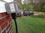
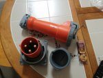
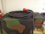
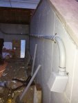
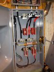
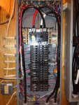
I have a Hubbell 100A reverse service plug on my house and a mating connector on the generator. I have a 200A transfer switch upstream of my main panel to allow for switching from grid power to back up power. 1awg THHN cable is run in conduit from the reverse service plug to the transfer switch. I also used 1awg cable to go from the generator to the plug. This cable is type W mining cable that supports currents well above 100A. I decided to go with a 100A set up just in case I wanted to upgrade the generator size in the future. I don't think I will at this point, but the costs weren't a huge amount more over a 60A set up.

Reverse service plug set:
IMG_2117.JPG

1 AWG Type W cable and plug on gen set. 1AWG with the high strand count is a tight fit on the output panel lugs, but they fit:
IMG_2713.JPG
IMG_2709.JPG

Conduit and back box (plug not installed yet in the pic), also, excuse the mess here, I was in the middle of reinsulating the rear overhang on my house and stuff was everywhere.
IMG_2404.JPG

Transfer switch wired up
IMG_2879.JPG
IMG_2892.JPG

Utility return alarm:
IMG_2893.JPG
 
Last edited:

Ray70

Well-known member
2,595
5,914
113
Location
West greenwich/RI
Chris, If you're having difficulty getting your 10/4 SOOW to stay securely in the lugs a simple fix might just be to just strip the end twice as long, fold the copper back over itself and twist it together to make it twice as thick. If you really want to go all out, tin the end with solder afterwards. There's plenty of other ways to make adapters and what not, but this might be a much simpler fix that is free!
 

Chrispyny

Member
294
12
18
Location
NY
Buy short pieces then use a set of split bolts sized to join #10 to #6.

You'll want to install a box with a 30a breaker between the generator and the #10 cable or reset the trip on the generator breaker for 30a.
My mep002a puts out 26 amps in single phase 240v. 10g wire is rated for this. And my generator already has a breaker on it. As well as the 30 amp breaker back feeding into my panel via factory interlock on my new square d qo panel.. Not really sure what you mean on either point?
 

Chrispyny

Member
294
12
18
Location
NY
Chris, If you're having difficulty getting your 10/4 SOOW to stay securely in the lugs a simple fix might just be to just strip the end twice as long, fold the copper back over itself and twist it together to make it twice as thick. If you really want to go all out, tin the end with solder afterwards. There's plenty of other ways to make adapters and what not, but this might be a much simpler fix that is free!
Thank you my friend. This is exactly what im going to do. I already have the tinning flux and solder. I just wanted a more professional termimation. But really,.what ever works well is key.

I also considered and may try flipping the contact bar in the split lug from the 'v' side to the 'flat' side.

In the end, i really should drill a hole on top of the cover to the power outlet box on the generator, and install a female L1430 outlet, and install a male l1430 on the generator end of my generator cable.
 
Last edited:

DieselAddict

Well-known member
Steel Soldiers Supporter
2,532
2,059
113
Location
Efland, NC
My mep002a puts out 26 amps in single phase 240v. 10g wire is rated for this. And my generator already has a breaker on it. As well as the 30 amp breaker back feeding into my panel via factory interlock on my new square d qo panel.. Not really sure what you mean on either point?
Ah. The discussion here originated about the 003. Did I miss where you stated it was an 002? If so I apologize.
 

gishooter

Member
32
1
8
Location
Ozarks
Lots of good discussions here. Does anyone else have pictures of the cables connecting to the terminals or similar? The reason I asked was my electrician suggested cutting a hole in the side of the box and using some kind of weather tight fitting. His concern was having the local inspector say no to the wires on the terminal posts and the box is easily opened. So has anyone done this or does everyone always use the original terminals?
Thanks,
Chris
 

DieselAddict

Well-known member
Steel Soldiers Supporter
2,532
2,059
113
Location
Efland, NC
I used the original terminals. You can add a hasp and a lock if you need.

I considered installing a conduit bushing in the side of the box and doing exactly what you are considering. In the end it was more effort for very little gain. The way the terminals are in there it doesn't leave a lot of room on the side to enter the box with a conduit large enough for three #6 wires. It would work but it would be tight in the top corner. I'll snap a photo of mine tomorrow.

One thing to do if you plan to have it inspected is to update the convenience outlet on the panel to a GFI. An inspector could fail you for that. I updated mine. It was NOT fun.
 
Top
AdBlock Detected

We get it, advertisements are annoying!

Sure, ad-blocking software does a great job at blocking ads, but it also blocks useful features of our website like our supporting vendors. Their ads help keep Steel Soldiers going. Please consider disabling your ad blockers for the site. Thanks!

I've Disabled AdBlock
No Thanks