• Steel Soldiers now has a few new forums, read more about it at: New Munitions Forums!

  • Microsoft MSN, Live, Hotmail, Outlook email users may not be receiving emails. We are working to resolve this issue. Please add support@steelsoldiers.com to your trusted contacts.

Engine Control Fuse Help

StoneyHill

Member
38
0
6
Location
Florence SC
I got a M1009 from Ft. Meade. Was not running. Replaced the batteries and a blown 20amp Engine Control Fuse. The truck then started and ran. I ran it a bit and then tried to start it later and the 20amp Engine Control fuse was blown again.

When the fuse is blown, the wait light will not come on and the truck will not start if cold.

I am trying to troubleshoot what could be blowing the fuse. I would love to find a diagram of what is in the Engine Control 20amp circuit. I have done a few searches and found the diagrams in the -20 TM. They are clear as mud.

I do not see the Engine Control fuse or circiut mentioned. Is there another place I need to look for a diagram of that circuit?

Has anyone else had problems with this fuse blowing? What was your solution.

Thanks for any help guys.
SCott
 

Warthog

Moderator
Super Moderator
Steel Soldiers Supporter
13,774
232
63
Location
OKC, OK
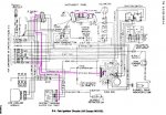
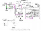
The fuse box diagram in in the Tech Manual TM 9-2320-289-20 Section 4-12. It is also shown in the FAQ Thread for CUCV's sticky at the top of the CUCV forum.

The wiring diagrams in the Appendix show the circuit for each fuse.You just need to look thru each diagram to find the correct fuse.

The #17 Engine Control Fuse supplies power to the following:

Seat belt warning buzzer
Instrument Cluster for the Temp, Low Coolant, Brake warning lights and the fuel gauge
Water In Fuel Solenoid
Cold Advance
Fast Idle

It could be a short in any of those wires.

You will need to learn to read the diagrams or pay someone to read them for you. The way I do it is to cut and paste a diagram and save it in Paint. I then draw a colored line for that circuit.

Read the first couple of pages of the troubleshooting section of the -20 or -34 for an explaination of how to read the diagrams.


It is a good idea to disconnect the batteries, remove all the fuses and clean the fusebox terminlas with Electrical Contact Cleaner and a small nail file or peice of sandpaper.

These trucks have been used and abused for the last 25+ years. The electrical conections get dirty and corroded
 

Attachments

StoneyHill

Member
38
0
6
Location
Florence SC
Warthog,

I wanted to say thank you very much for helping me with this. I know you get tired of the new guys asking what seem like simple questions.

I was so frustrated when i posted that. I guess I could have spent some more time researching the diagrams.

Thanks again.

SCott Burns
 

kcbbqguru

New member
89
0
0
Location
kansas city
Thanks for all you guys help! My fuel gauge quit working this morning, then when I got home glow plug relay would not work. I tracked down #17 fuse and it was blown, went to wally world and bought some fuses, cleaned everything up real goood, and put some dielectric grease on it and sure enough fuel gauge worked, glow plug light on, and then it fired right up, thanks again
 

Naqeeb

New member
13
0
0
Location
Portland , Wisconsin
Pursuant to Warthog's above post, I have begun trying to find the short/ground that keeps blowing fuse #17 in my 1986 M1009 (it blew a 75 amp one, too). Checking for continuity at the end of the fast idle solenoid, I find the circuit is closed. Confused, I checked it on a perfectly working 1984 M1009...same result, the circuit is closed. I must not understand the operation of this; I assumed it would be open (key in “off” position, batteries disconnected.). That aside, I pulled fuse #17 out and checked for continuity on both sides of where the fuse plugs in. On the working M1009, the left side has a closed circuit and the right side does not. In the malfunctioning M1009, both sides have a closed circuit. I am assuming this is the problem. On both CUCVs the left three terminals of the seatbelt buzzer have a close circuit, which makes me rule out this as being the problem. At this point, not clear on the fast-idle solenoid, I am unclear where to check next. I am guessing this is not the problem since the result is the same on both trucks.

Of the five items Warthog lists as running off of #17, should none of them have continuity? My thinking was that if one showed a closed circuit, that was where the short was. The fast-idle solenoid makes me question this. I am a little unclear what the correct behavior should be on each wire.
 

Warthog

Moderator
Super Moderator
Steel Soldiers Supporter
13,774
232
63
Location
OKC, OK
Check the wiring at the coolant temp switch on the passenger rear head. Many times the wires will melt and cause a short.

This sensor controls the fast idle and cold advance.
 

Naqeeb

New member
13
0
0
Location
Portland , Wisconsin
Hasdrubal: I put a 75 amp fuse in #17. Bad idea since it calls for a 20 and I could have ruined something, but it did illustrate to me that the issue is probably a wire shorting out, not some small gremlin. #17 is the one that blew.
Warthog: I will check the wiring you suggest.

Thank you both for your input.
 

Naqeeb

New member
13
0
0
Location
Portland , Wisconsin
Both wires look free of damage and in good condition; have not looked in the loom yet. Continuity testing reveals both wires on coolant temp switch (green and PNK/BLK...the pink looks more tan to me) have closed circuits to ground each, when green fast idle solenoid and cold advance are plugged in. Green wire has open circuit to ground when both cold advance and fast idle are unplugged (as expected). There is a closed circuit to ground on bare tangs (wires not put on them) for cold advance and fast idle both. On the working M1009, only the cold advance solenoid has a closed circuit to ground; the fast idle does not.

After following the circuit for .8 PNK/BLK 39A in the TM from the “COLD ADVANCE & IDLE SW” all the way to the fuse box, I see now why the right side of the fuse is showing a closed circuit to ground if the tangs on the fast idle and cold advance have a closed circuit to ground themselves (assuming the coolant temp switch is a closed circuit). To verify this is a/the source of ground in #17 fuse on the right side; with fast idle, cold advance, and the temp switch all unplugged, the right side of fuse #17 still shows a closed circuit to ground; not what I expected thinking the source for ground was the tangs (and the short somewhere on the wire). The working M1009 has a closed circuit to ground from the PNK/BLK on the temp switch as well. I did retest both sides of #17 fuse in the working CUCV, both sides do have closed circuit to ground, contrary to what I posed earlier. I am going to investigate PNK/BLK wire further since I can not rule it out as being the short, even though the working M1009 has ground on this wire at the coolant temp switch. As for the tangs on the fast idle and cold advance having ground, it did blow fuse #17 with them unplugged, so they are not the [only] problem. Also, on the working M1009, there is a closed circuit from green to PNK/BLK wires for the coolant temp switch, but not on the malfunctioning one. I would have though this would have been the other way around. I am going to measure the resistance to ground on the PNK/BLK at the coolant temp switch and see if there is a difference between the working and non-working CUCV.
 

MarcusOReallyus

Well-known member
4,524
816
113
Location
Virginia
Hasdrubal: I put a 75 amp fuse in #17. Bad idea since it calls for a 20 and I could have ruined something, but it did illustrate to me that the issue is probably a wire shorting out, not some small gremlin. #17 is the one that blew..
The fact that the proper fuse blew already told you that you have a short. Putting a higher amperage fuze in as a test is a really, really bad idea.

Really bad.

As in, don't ever do that.


And did I mention that it's a really bad idea?
 

porkysplace

Well-known member
Steel Soldiers Supporter
9,604
1,493
113
Location
mid- michigan
The fact that the proper fuse blew already told you that you have a short. Putting a higher amperage fuze in as a test is a really, really bad idea.

Really bad.

As in, don't ever do that.


And did I mention that it's a really bad idea?
It makes it easier to find the short , just look for the smoke.
 

Keith_J

Well-known member
3,657
1,323
113
Location
Schertz TX
Even on these ATC fuses, bad contacts can cause heating of the blades which heats the fuse element which then causes it to blow at lower than rated current. The old tube style were even worse at this problem as the elements were soldered to the end caps, solder melts and the fuse fails in a hidden mode.

something to check, clean and proper spring tension of the clips. ATC fuses that are easily extracted point to weak connections which will cause trouble. Yes, you can retension the clips without pulling the box. Just be safe and disconnect the batteries before sticking small screwdrivers in behind the clips.
 

Naqeeb

New member
13
0
0
Location
Portland , Wisconsin
Keith_J, I checked the pressure the clips in the fuse box are applying to the tangs on the fuse; both sides pretty tight. Takes a bit of effort to pull the fuse out.
 

Naqeeb

New member
13
0
0
Location
Portland , Wisconsin
My short ended up being the coolant temp switch for fast idle and timing advance. One of the tangs was grounded. The replacement fixed it; 20 amp fuse no longer blows.
 
Top
AdBlock Detected

We get it, advertisements are annoying!

Sure, ad-blocking software does a great job at blocking ads, but it also blocks useful features of our website like our supporting vendors. Their ads help keep Steel Soldiers going. Please consider disabling your ad blockers for the site. Thanks!

I've Disabled AdBlock
No Thanks