• Steel Soldiers now has a few new forums, read more about it at: New Munitions Forums!

  • Microsoft MSN, Live, Hotmail, Outlook email users may not be receiving emails. We are working to resolve this issue. Please add support@steelsoldiers.com to your trusted contacts.

Custom Making LED Light Bar for M939

74M35A2

Well-known member
4,145
332
83
Location
Livonia, MI
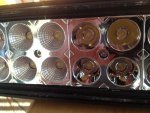
Here is the 70" LED light bar assembled with all reflectors, just waiting for the lens to arrive. Also included a shot of the difference of flood vs spot reflectors. Flood reflectors are on each end, with spot reflectors in the middle.
 

Attachments

74M35A2

Well-known member
4,145
332
83
Location
Livonia, MI
Well, a short term set back. The light bar is together (sans lens) and works, but makes a loud buzzing/hissing sound when supplied with 24V. On 12V, there is no noise. The bar is supposed to be able to handle 12-30V range. It seems as if one of the voltage regulators on one of the light module circuit boards is just not happy dropping the 24V down to the level it needs. I'll need to pull all the reflectors off, and see if I can determine which light module board is not happy. May need to disassemble completely, and test each module on 24V. If only one board has a flunky voltage regulator, then I will buy another (3rd) light bar, possibly shorter, and swap out the funky board, then reassemble.

Even though it is LED, it makes a lot of light and puts off a lot of heat, especially when only 6" away from it during working on it.
 

tim292stro

Well-known member
2,118
41
48
Location
S.F. Bay Area/California
Hopefully its not a resonance or oscillation do to the count of LED regulators. If that's the case however, you can always add capacitors to the inputs for each board and inductors to the supply lines to cut down on the AC component on the power rail. I've also found that cheap un-shielded inductors with cheap cores tend to "sing". You might just be hearing the power supply doing its job in an open case (with no cover, which would normally trap the sound inside the housing - outside your vehicle).

https://www.youtube.com/watch?v=T7HsXHqtxrI
 

74M35A2

Well-known member
4,145
332
83
Location
Livonia, MI
Thanks for the input Tim, we'll see. It is way louder than it is supposed to be and the LED's flicker also when on 24V. On 12V, the light is silent and non-flickering if I use one ground wire, but not another which I added, but at 12V it is sucking about 40A like it should be so I can't run it long because even the 12ga wires I used get warm obviously. On 24V, it should be about 17-18 amps or so, which should be tolerable for 12ga wire.

If each board tests OK individually on 24V, then it is likely a harmonic issue as you indicated. If you have recommendations for dampening (capacitor or inductor values), I'm all ears. I ran the power lead to the center board first, as to not over-load the daisy chain of boards by feeding from one end, as they did with 5 boards when the light bar was 50" wide as new.
 

tim292stro

Well-known member
2,118
41
48
Location
S.F. Bay Area/California
12Ga is right on the threshold for 420W @ 24VDC, dual 12Ga left/right half, or take out the floods on the side and do spot and flood power rails to reduce the current would be recommended. Normally we use 300 circular mils/amp and less than 1/2V (0.5V) drop (loss) over the wire for safety. At 18A, you're at 360 circular-mils (cutting it pretty close), and about 0.57V drop over the wire (so it will get warm).

If you changed the wire to 10Ga for a single circuit on the whole fixture, you'd have 575 circular-mills (91% safety margin), and a voltage drop of only 0.36V over the wire.

I'm not sure exactly what your split is on spot/flood, but if you do 12Ga (power/ground) with the flood and 10Ga (power/ground) with the spot you should be golden [thumbzup]


[EDIT:] To help out with the harmonic issue if that becomes the target of your root-cause, I'd need to know the operating frequency of the LED power supply - I see from your signature that you work somewhere that might have an oscilloscope or a spectrum analyzer, a hardware engineer should be able to take a spot measurement for you in a few seconds. After that it's as simple as designing you a low-pass filter that's at least 3x below the operating frequency.

It should also be noted that the resistance of the wire if significant (as it appears to be in your case) can contribute to sub-harmonics becoming a factor in your series circuit[/EDIT]
 
Last edited:

74M35A2

Well-known member
4,145
332
83
Location
Livonia, MI
I'm ok with the wiring right now. I want to get the lamp modules working correctly and then conduct a measurement, and size accordingly.

Each LED is 3W, and there are 140 of them. Just FYI. Stay tuned, thanks.
 

Hainebd

New member
520
5
0
Location
Mays Landing, NJ
You people never cease to amaze me with your skills and knowledge. Great job just can understand how you can wait to finish. Get the thing done and post pictures of it mounted. Some of us need to borrow others ideas cause they are Kool. Thank you for the write up.
 

74M35A2

Well-known member
4,145
332
83
Location
Livonia, MI
Thanks bud. Sorry for the hang up. We'll get through this, and then everybody will be able to do it also. Full width LED light bars front and rear for $200! When I had it on, it was like having the sun screwed onto to your truck.

Pics coming as soon as we have it working correctly. It's close.

Cool TJ. I did the starter, alternator, battery, and all engine sensors when it was developed.
 
Last edited:

74M35A2

Well-known member
4,145
332
83
Location
Livonia, MI
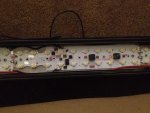
One of the light modules. They are chained together to feed power through, in addition to a leap-frog of power wires so lessen the load on each solder bridge. It was configured this way initially, so I simply continued it.

image.jpg
 

BobbyT

Member
65
37
18
Location
Little Rock, Arkansas
74M, you should look at painting the flat front reflectors a flat black so there isn't so much shiny chrome on a dark flat MV. You should be able to take a smooth small foam roller and roll a few light coats on each module without affecting the actual reflector with runs. I think it would look better than a giant bar of chrome across the top, help it blend in more. Similar to this picture.
image.jpg

Great work so far.
 

74M35A2

Well-known member
4,145
332
83
Location
Livonia, MI
74M, you should look at painting the flat front reflectors a flat black so there isn't so much shiny chrome on a dark flat MV. You should be able to take a smooth small foam roller and roll a few light coats on each module without affecting the actual reflector with runs. I think it would look better than a giant bar of chrome across the top, help it blend in more. Similar to this picture.
View attachment 549089

Great work so far.
Thanks. That is a good idea. I'll consider it before I reassemble it.
 

74M35A2

Well-known member
4,145
332
83
Location
Livonia, MI
Relay for sure. I upped the wattage of my bar from 300W to 420W by extending it, so that is going to be between 15-20 amps depending upon system voltage. Given that, I'll use a 30A relay, which is a standard cube relay, but make sure the coil side is 24V. Relays for rear defrost grids and glow plugs are higher rated if need be.
 
Top
AdBlock Detected

We get it, advertisements are annoying!

Sure, ad-blocking software does a great job at blocking ads, but it also blocks useful features of our website like our supporting vendors. Their ads help keep Steel Soldiers going. Please consider disabling your ad blockers for the site. Thanks!

I've Disabled AdBlock
No Thanks