- 2,333
- 4,206
- 113
- Location
- Massachusetts
Another thread here inspired me to design and build a remote start and generator parameter reporting system for my 802 to use in conjunction with my PV battery bank solar charging system and thought this may be of interest to other Mep owners.
I've designed, built and coded the 802 Autostart controller utilizing a Arduino Mega 2650 controller.
The Mega was required due to the amount of digital I/O required. Verified the wireless remote start/stop capability as well as the wireless remote parameter monitoring.
Generator operating parameters monitored and wirelessly reported are:
- Oil Pressure
- Coolant Temp
- Fuel Level
- 802 Battery Voltage
- Battery Charge/Discharge
- AC Output voltage
- AC Frequency
- % Load
- Aux Fuel Pump Enable Status
All sensor outputs are measured via the Arduino's 16 channel A/D converter.
Sensor readings are wirelessly transmitted to the Battery Bank controller for display inside the house.
All sensors except the transformer are mounted on a daughter board ("shield") plugged into the Arduino Mega.
Power for the 802 Autostart controller is controlled by the 802's dead crank switch.
6 relays are tied to the 802 to control the RUN, START, PREHEAT, CONTACTOR CLOSE, CONTACTOR OPEN & AUX FUEL PUMP functions.
Commanding the generators controller is a Arduino based controller that monitors my PV battery bank voltages.
It monitors the individual batteries and the total bank voltage (48 volts). All individual battery voltages as well as the overall bank voltage is displayed on a LCD screen on the controller. When the battery bank voltage drops below a threshold voltage it talks wirelessly to the 802 to see if it's ready for a remote start. If ready it then sends a remote START command wirelessly to the 802. Once the 802 controller receives the START from the battery bank monitor it Primes the 802, does a PreHeat if below 40 F, Starts the generator, Warms it up and then closes the Contactor. It also enables the Aux Fuel Pump if it has been selected.
It attempts 3 starts before timing out.
Oil pressure is used to determine if the genset has successfully started. If it fails to start after 3 tries it times out and a Start failure is reported back to the Battery Bank controller and is displayed on it's LCD screen.
While running it reports all genset operating parameters wirelessly back to the PV battery monitoring system in the house. The PV battery monitor inside the house displays the 802's Oil Pressure, Temperature, Fuel Level, 802 Battery Voltage, 802 Battery Charge/Discharge, % Load, Frequency, 802 AC Output Voltage and Aux Fuel Pump Enable status.
Once the PV battery bank has completed charging the battery monitor sends a STOP wirelessly to the 802. The 802's controller then opens the contactor, allows the generator to run 5 minutes to cool the gen head and then stops the 802.
It then awaits the next START command from the PV battery monitor.
Below is a video of one of my initial check out runs and a few pictures.
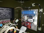
AutoStart Controller, parameter sensor and RF transceiver mounted in the 802.

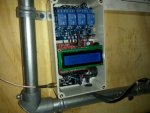
PV Battery Bank Monitor in the garage. Blue relays will be used to select voltages from future additional batteries.

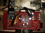
Close up of the Generator parameter sensor board and RF transceiver.
LED's used to indicate controller status (mostly used for integration)

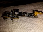
2.4GHz nRF24L01+PNA+LNA Tranceivers used. Shown mounted to power a 5 v to 3.3 v regulator assembly.

** I still need to tweek the firmware to correctly scale the operating parameters displayed so don't beat me up for an odd looking parameter display value.
The time delay for Warm Up before Contactor Close is shortened for the purpose of checkout and this video.
A video of one of my test runs.
https://www.youtube.com/watch?v=51PjzkTsGhA
Enjoy!
Kurt
I've designed, built and coded the 802 Autostart controller utilizing a Arduino Mega 2650 controller.
The Mega was required due to the amount of digital I/O required. Verified the wireless remote start/stop capability as well as the wireless remote parameter monitoring.
Generator operating parameters monitored and wirelessly reported are:
- Oil Pressure
- Coolant Temp
- Fuel Level
- 802 Battery Voltage
- Battery Charge/Discharge
- AC Output voltage
- AC Frequency
- % Load
- Aux Fuel Pump Enable Status
All sensor outputs are measured via the Arduino's 16 channel A/D converter.
Sensor readings are wirelessly transmitted to the Battery Bank controller for display inside the house.
All sensors except the transformer are mounted on a daughter board ("shield") plugged into the Arduino Mega.
Power for the 802 Autostart controller is controlled by the 802's dead crank switch.
6 relays are tied to the 802 to control the RUN, START, PREHEAT, CONTACTOR CLOSE, CONTACTOR OPEN & AUX FUEL PUMP functions.
Commanding the generators controller is a Arduino based controller that monitors my PV battery bank voltages.
It monitors the individual batteries and the total bank voltage (48 volts). All individual battery voltages as well as the overall bank voltage is displayed on a LCD screen on the controller. When the battery bank voltage drops below a threshold voltage it talks wirelessly to the 802 to see if it's ready for a remote start. If ready it then sends a remote START command wirelessly to the 802. Once the 802 controller receives the START from the battery bank monitor it Primes the 802, does a PreHeat if below 40 F, Starts the generator, Warms it up and then closes the Contactor. It also enables the Aux Fuel Pump if it has been selected.
It attempts 3 starts before timing out.
Oil pressure is used to determine if the genset has successfully started. If it fails to start after 3 tries it times out and a Start failure is reported back to the Battery Bank controller and is displayed on it's LCD screen.
While running it reports all genset operating parameters wirelessly back to the PV battery monitoring system in the house. The PV battery monitor inside the house displays the 802's Oil Pressure, Temperature, Fuel Level, 802 Battery Voltage, 802 Battery Charge/Discharge, % Load, Frequency, 802 AC Output Voltage and Aux Fuel Pump Enable status.
Once the PV battery bank has completed charging the battery monitor sends a STOP wirelessly to the 802. The 802's controller then opens the contactor, allows the generator to run 5 minutes to cool the gen head and then stops the 802.
It then awaits the next START command from the PV battery monitor.
Below is a video of one of my initial check out runs and a few pictures.
AutoStart Controller, parameter sensor and RF transceiver mounted in the 802.

PV Battery Bank Monitor in the garage. Blue relays will be used to select voltages from future additional batteries.

Close up of the Generator parameter sensor board and RF transceiver.
LED's used to indicate controller status (mostly used for integration)

2.4GHz nRF24L01+PNA+LNA Tranceivers used. Shown mounted to power a 5 v to 3.3 v regulator assembly.

** I still need to tweek the firmware to correctly scale the operating parameters displayed so don't beat me up for an odd looking parameter display value.
The time delay for Warm Up before Contactor Close is shortened for the purpose of checkout and this video.
A video of one of my test runs.
https://www.youtube.com/watch?v=51PjzkTsGhA
Enjoy!
Kurt


 hectic here.