• Steel Soldiers now has a few new forums, read more about it at: New Munitions Forums!

  • Microsoft MSN, Live, Hotmail, Outlook email users may not be receiving emails. We are working to resolve this issue. Please add support@steelsoldiers.com to your trusted contacts.

Wireless AutoStart with Remote Parameter Monitoring

kloppk

Well-known member
Steel Soldiers Supporter
2,145
3,526
113
Location
Pepperell, Massachusetts
Another thread here inspired me to design and build a remote start and generator parameter reporting system for my 802 to use in conjunction with my PV battery bank solar charging system and thought this may be of interest to other Mep owners.

I've designed, built and coded the 802 Autostart controller utilizing a Arduino Mega 2650 controller.
The Mega was required due to the amount of digital I/O required. Verified the wireless remote start/stop capability as well as the wireless remote parameter monitoring.
Generator operating parameters monitored and wirelessly reported are:
- Oil Pressure
- Coolant Temp
- Fuel Level
- 802 Battery Voltage
- Battery Charge/Discharge
- AC Output voltage
- AC Frequency
- % Load
- Aux Fuel Pump Enable Status

All sensor outputs are measured via the Arduino's 16 channel A/D converter.
Sensor readings are wirelessly transmitted to the Battery Bank controller for display inside the house.
All sensors except the transformer are mounted on a daughter board ("shield") plugged into the Arduino Mega.
Power for the 802 Autostart controller is controlled by the 802's dead crank switch.
6 relays are tied to the 802 to control the RUN, START, PREHEAT, CONTACTOR CLOSE, CONTACTOR OPEN & AUX FUEL PUMP functions.

Commanding the generators controller is a Arduino based controller that monitors my PV battery bank voltages.
It monitors the individual batteries and the total bank voltage (48 volts). All individual battery voltages as well as the overall bank voltage is displayed on a LCD screen on the controller. When the battery bank voltage drops below a threshold voltage it talks wirelessly to the 802 to see if it's ready for a remote start. If ready it then sends a remote START command wirelessly to the 802. Once the 802 controller receives the START from the battery bank monitor it Primes the 802, does a PreHeat if below 40 F, Starts the generator, Warms it up and then closes the Contactor. It also enables the Aux Fuel Pump if it has been selected.
It attempts 3 starts before timing out.
Oil pressure is used to determine if the genset has successfully started. If it fails to start after 3 tries it times out and a Start failure is reported back to the Battery Bank controller and is displayed on it's LCD screen.

While running it reports all genset operating parameters wirelessly back to the PV battery monitoring system in the house. The PV battery monitor inside the house displays the 802's Oil Pressure, Temperature, Fuel Level, 802 Battery Voltage, 802 Battery Charge/Discharge, % Load, Frequency, 802 AC Output Voltage and Aux Fuel Pump Enable status.

Once the PV battery bank has completed charging the battery monitor sends a STOP wirelessly to the 802. The 802's controller then opens the contactor, allows the generator to run 5 minutes to cool the gen head and then stops the 802.
It then awaits the next START command from the PV battery monitor.

Below is a video of one of my initial check out runs and a few pictures.


AutoStart Controller, parameter sensor and RF transceiver mounted in the 802.
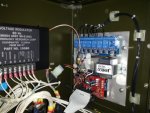
20160203_133241.jpg


PV Battery Bank Monitor in the garage. Blue relays will be used to select voltages from future additional batteries.
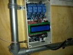
20160211_141551.jpg

Close up of the Generator parameter sensor board and RF transceiver.
LED's used to indicate controller status (mostly used for integration)
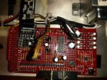
20160203_130514.jpg

2.4GHz nRF24L01+PNA+LNA Tranceivers used. Shown mounted to power a 5 v to 3.3 v regulator assembly.
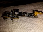
20160120_143251.jpg


** I still need to tweek the firmware to correctly scale the operating parameters displayed so don't beat me up for an odd looking parameter display value. :lol:
The time delay for Warm Up before Contactor Close is shortened for the purpose of checkout and this video.

A video of one of my test runs.
https://www.youtube.com/watch?v=51PjzkTsGhA

Enjoy!

Kurt
 

kloppk

Well-known member
Steel Soldiers Supporter
2,145
3,526
113
Location
Pepperell, Massachusetts
BobbyT - Nice Jeep! I'm also into off roading. 1992 YJ 4 linked, tons, 43" stickies, cage, winch's,...

I have no plans to sell a "kit".

However I'd be happy to share any and all information I have about each of the controllers, how to build them, program them, firmware files and how to connect them up to the genset, etc. People are certainly welcome to leverage off of any information for their own use or designs.
I also have a lot more pictures that may be of help.

Here is a quick list of the parts, what they cost and where to get them.

Battery Controller - Parts Cost
- Arduino UNO Microcontroller $10
- Arduino Prototyping Daughter Card (Shield) Set of 3 $13
- Relay Board with 4 relays $7
- LCD Display $6
- nRF24L01+PNA+LNA 2.4 GHZ Tranceiver $11
- RP-SMA RF Cable $5
- 5 volt to 3.3 volt regulator assembly $4
Total $56

Generator AutoStart Controller - Parts Cost
- Arduino MEGA 2650 Microcontroller - $18
- Arduino Prototyping Daughter Card (Shield) $8
- Relay Board with 8 relays $10
- RP-SMA RF Cable $5
- nRF24L01+PNA+LNA 2.4 GHZ Tranceiver $11
- 5 volt to 3.3 volt regulator assembly $4
- Transformer 240 Volt to 3.3 Volt $11
- INA125 Differential Amplifier $6
Total $73

Misc Parts purchased for both builds.
Only used a small amount of what was purchased. Lot's of leftovers for other projects.
- Assortment of Resistors $10
- Assortment of Capacitors $20
- Assortment of Diodes, LED's, Transistors, Variable Resistors $17
- Set of 10 LM7812 Regulators $7 (only needed 1)
Total $54

All parts purchased from Amazon except...
- Transformer from Jameco Electronics
- INA125 Differential Amplifier from DigiKey

Misc stuff I had on hand laying around my shop
- Molex connector pair (disc drive power connectors salvaged from an old PC)
- Wire
- Wire Lugs
- Ribbon cable w/ connector (PC IDE disc drive ribbon cable salvaged from an old PC)
- Shrink Tubing
- Nuts, bolts, cable ties, cable clamps, sheet metal

If anyone wants additional just let me know.
 
Last edited:

CT-Mike

New member
238
2
0
Location
CT
Kurt,

Awesome work. I have started on something similar using the 2560, but I haven't gotten very far due to work and other commitments. If you don't mind I will PM you my email address. Please send any photos, schematics, wiring diagrams, instructions, etc that you may have. This will save me a lot of work.

I don't need a battery controller, but I am looking for wireless remote start, parameter monitoring, and have the Arduino host a web server so that I can check on how the machine is doing using my iPad.

I take it that you just tapped off the rear of the installed meters since you don't have any sensors listed in your parts list?

Thanks,

Mike
 

kloppk

Well-known member
Steel Soldiers Supporter
2,145
3,526
113
Location
Pepperell, Massachusetts
Mike,

Got your PM. Will send you what I have for info as well as the Auduino code for both controllers.
The code is still in beta testing so it is not 100%. Been too cold to work on some of the details.
Also there are tid bits in the code for debugging and some time delays shortened.
It was my first project using C++ so you may want to change it to you own programming style..

As for sensors I did the following to get the operating parameters:

- Oil pressure: Measure the DC voltage at the "S" pin on the meter. Goes thru a resistor divider on the Aurduino daughter board then to the A/D.

- Fuel Level: Measure the DC voltage at the "S" pin on the meter Goes thru a resistor divider on the Aurduino daughter board then to the A/D.

- Temperature: Measure the DC voltage at the "S" pin on the meter. Goes thru a resistor divider on the Aurduino daughter board then to the A/D.

- Battery Voltage: Measure DC voltage supplied to power the controller. Power supplied from MEP S2's common terminal.

- AC Output Voltage: 240VAC to 3.3 VAC Transformer. Transformer primary connected to the back of the Voltmeter Terminals.
One side of the transformer secondary is tied to GND. Other leg goes to the A/D. Aurduino does a peak voltage detect routine to determine output voltage.

- AC Frequency: Same Transformer as above. Auduino does a peak to peak timing measurement on the 3.3 VAC sinusoidal signal to determine frequency.

- Charge Current: Measures the slight differential voltage across the MEP's MT4 shunt. Differential voltage is amplified using an INA125 differential amplifier. It's single ended output goes to the A/D.

- %Load: Voltage across burden resistor R11 go thru a full wave bridge rectifier, is filtered and resultant DC voltage goes to the A/D

All voltages into the A/D are scaled with a calibration factor to determine each of the operating parameters.
 
Last edited:

kloppk

Well-known member
Steel Soldiers Supporter
2,145
3,526
113
Location
Pepperell, Massachusetts
The solar battery bank is a set of 8 deep cycle 12 volt FLA 90 AH batteries connected in series and parallel to create a 48 volt 180 AH battery bank.
It's four pairs of 12 volt batteries connected in parallel and then the 4 sets tied in series.
Planning to replace the battery bank this summer with a set of higher capacity batteries such as 370 AH 6 Volt L16's as the current batteries are 5+ years old.
This upgrade should at least double my autonomous run time. Probably more as the old batteries are getting tired.

There is a 1,700 watt solar panel array feeding a Morningstar TSMPPT60 MPPT charge controller which in turn charges the 48 volt battery bank. This is always connected to the batteries. There is no need to disconnect the charge controller when the genset & inverter charger are also charging the battery bank.

The battery bank feeds 48 volt power to an inverter charger. When utilities are up the inverter charger can assist with recharging the bank if I enable utility power to it if the solar panels can't keep up. I usually do some load management with my transfer switch panel to keep the inverter load on par with the solar output so that I'm not recharging with utility power.

When the utilities are down the MEP-802A can be connected to the inverter chargers AC input and the AutoStart system can be then be enabled.
When the utilities are down there will be a much greater demand on the battery bank so the genset will need to kick on occasionally to recharge the bank before they get drawn down too low. At night the Autostart can be disabled so that I can power the essentials at night off the battery bank and have peace & quiet. I don't like to hear the drone of a generator all night long and neither would my neighbors.
 

kloppk

Well-known member
Steel Soldiers Supporter
2,145
3,526
113
Location
Pepperell, Massachusetts
To be honest I haven't gotten back to it. Let's just say life here has been :cookoo: hectic here.
Not conducive to making a lot of racket running the genset just outside the house.
Probably June 1st before I get back to seriously working on the project.
 

OverkillTASF

Member
92
6
8
Location
Central Virginia
Love it and will be sure to reference this in future! Will probably try to duplicate most of this effort with the MEP-831A...

Question about the Midnite chargers... What do you think about their ability to, say.... accept rectified 3 phase 200 VAC from the MEP-831A PMA? I'm reaching out to some wind nuts on the Internet since they have more familiarity with doing useful things with alternator output... but since I mainly bought my generator to supplement / cover for a future solar setup (current one is far too small to worry about), it made some kind of elegant sense to look at skipping all the inverter crap and just having 3KW of high voltage DC to work with...
 

kb3bf

Member
127
2
16
Location
Howard County Md.
Hi KLOPPK

I have been toying with the idea of building a remote control for the MEP-802A like yours, however at present I don't have a battery bank installed (I will likely get one later driving a pair of 3.6KW Outbacks); I am pondering what the remote control circuit should consist of for now.

I am interested in going over your Arduino project details, with the same starting sequence and getting any info/advice you may be able to offer, including any circuit board details and images you may have, but hopefully without you spending too much time on your part. I am hoping you may already have a duplicate writeup of your setup. Is it listed somewhere?
(I have good RF/AC circuits background, but only basic programming skills).

many thanks in advance, kb3bf(at)ARRL(dot)NET
 
Last edited:

kloppk

Well-known member
Steel Soldiers Supporter
2,145
3,526
113
Location
Pepperell, Massachusetts
kb3bf

Sent you an email with a number of pictures, design info and my firmware that I'm beta testing.

The programming is in C++. First time I used C++ was for this project.
Pretty easy to pick up once. Lot's of good syntax reference help on the Auduino website.
I commented the heck out of the firmware so it should be fairly clear what each segment of code does.

Let me know if I can provide any additional info!

Kurt
 
Last edited:

kb3bf

Member
127
2
16
Location
Howard County Md.
Many thanks Kurt.
AWSOME INFO!
I am starting the parts gathering process.
I will document the project here also, albeit over some time. It will be a long, long one.
kb3bf
 

kb3bf

Member
127
2
16
Location
Howard County Md.
Zep is hot stuff!

87Nassaublue, YOU ARE THE MAN!

Time to buy more of that ZEP rust neutralizer!

It worked. it took some 18hrs of soaking for the solenoid to come loose.

Had you not come forward with the ZEP advice I was going to toss K1 as a lost cause.

That relay deserves being repaired. It is rated for 150AMPS.
Like I said before DW40 did not work because I only have spray cans and I did not think of emptying several cans into the soaking jar.

I still have more work to do and I am not out of the woods yet, but I am much better off with the solenoid parts separated. I am going to keep it soaked in the jar for a little longer, until the rust is further reduced.

MEP owners: check your K1s for possible gasket failures. Lubricate the solenoid if necessary for a longer relay life.
It is easy to take apart.

kb3bf
 

Attachments

Top
AdBlock Detected

We get it, advertisements are annoying!

Sure, ad-blocking software does a great job at blocking ads, but it also blocks useful features of our website like our supporting vendors. Their ads help keep Steel Soldiers going. Please consider disabling your ad blockers for the site. Thanks!

I've Disabled AdBlock
No Thanks