• Steel Soldiers now has a few new forums, read more about it at: New Munitions Forums!

  • Microsoft MSN, Live, Hotmail, Outlook email users may not be receiving emails. We are working to resolve this issue. Please add support@steelsoldiers.com to your trusted contacts.

New FLU419 Owner, Electrical Woes

Jon Walker

Member
31
1
6
Location
Cedar City, Utah
I purchased a FLU419 over the weekend, it is amazing! My engine starts instantly and runs great, trans is solid, hydraulics and hydraulic tools work well. My problem is that no electrical system is working. I replaced all the relays and fuses I could find. My on dash voltmeter does not read any current.aua

I saw a youtube video about replacing a relay hidden under the alternator.

Any other ideas on what it could be?
 

The FLU farm

Well-known member
Steel Soldiers Supporter
3,341
1,328
113
Location
The actual midwest, NM.
Welcome, Jon!

You may want to be more precise (at least when dealing with me). If "no electrical system is working" I wouldn't expect a SEE to start, let alone activate the tool circuit. And now that you got me going; there won't be any current showing on a Volt meter. It'll take an Amp meter to show current.

With that out of the way, is your charging light on? My "Winter SEE" doesn't start charging until the revs get up there a ways - and then it likes to over charge, but that's a different story. Or maybe not.

I have good reason to believe that the regulator behind the alternator is to blame, and it could be part of the cause in your case, too. But the Volt meter should still show battery voltage whether the charging system works or not.
Unfortunately, many (okay, most) recent GP sales of FLUs came complete with rodent damage to the wiring. It's really only a matter of how extensive it is.

Then again, not knowing if your SEE was from a recent auction or a private sale, that's pure speculation on my part.
 

peakbagger

Well-known member
734
360
63
Location
northern nh
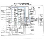
This link is going to lead you to the electrical diagram https://www.steelsoldiers.com/showthread.php?168054-Unimog-FLU-419-SEE-Wiring-Diagram. Best idea is copy it on a USB stick and bring it to Staples and have it printed out as large as they can print it (24 x 36 recommended). There was (or is) a recent listing on Ebay for copy of the diagram which is worth buying as its plastic laminated. There is a very good electrical diagnostic troubleshooting section in the technical manuals.

I think I was the first unlucky one to find rodent damage on the forum, I initially thought it was an odd one off situation but many others have found it, some far worse than mine. The problem is the rodents nest almost directly behind the gauges behind the dash and its almost impossible to see it unless you remove the air inlet duct work behind the fuse box. Mine would start and run but most of the electrical accessories would not work. I hope this is not your case, if it is, plan on weeks of work chasing down circuits or just not fixing it and hoping the gnawed wires don't short.
 

Jon Walker

Member
31
1
6
Location
Cedar City, Utah
I tried printing that diagram 5 times last night, it needs to be printed at staples like you said. I found rodent poop on the passenger side floor, but so far have been unable to find any damaged wires. I will probably pull the alternator and volt meter that relay.
 

peakbagger

Well-known member
734
360
63
Location
northern nh
Uh-oh, hopefully the rats were kind. They gnawed right through my main harness behind the Tach. 21 wires total meaning 42 ends to connect up and all the wires are black. I was lucky, some folks got SEEs that the rats had gnawed the main electrical connectors. I did it without the wiring diagram by using the electrical diagnosis section of the manuals. I would suggest removing the front end loader so you can get under the hood. (I did it with the loader attached and its a real PITA) From there you can unscrew the fuse block from the body and then take out the defroster ducts (which are easy to damage) and then the air intake ducts. At that point you will probably find a rats nest and gnawed off wires. I strongly suggest taking the gauges out of the dash by carefully removing the mounting brackets an not dropping the hardware so you have some room. From there its just down to going though system by system reconnecting the wires one by one by tracing the right pin on the main connectors behind the fuse box and where the wire comes from the dash. You will find that its best to work on a few circuits at a setting and then take a break. I don't think I would fix anyone else's even at my normal charge out rate of $170 an hour ;)


The wiring diagrams were unavailable anywhere until one of the Steel Soldiers members, General Hood graciously bought a pallet full of junk at an auction just to get a roll of these wiring diagrams.
 

rtrask

Well-known member
342
251
63
Location
San Luis Valley, Colorado
Hi Jon,
Welcome to the group.

I am a relatively new member, and I am in much the same boat as you. I bought mine at auction in May with the intent of having it ready to go next spring. I had a lot of issues getting mine delivered, and since it is not critical to my life until next spring, it was largely put on the back burner.
I am now getting more serious about it as I have time.

That said I hate electrical problems, which may be why I have been putting off dealing with mine. I think I may have fixed the Oil Pressure sensor just because I found some broken wires, and an issue with the sensor itself. I am going to hack a solution for that. I think the best advice anyone can give you is not to look for a silver bullet that solves all your problems, but instead go about it systematically. Get a copy of the Technical Manual TM 5-2420-224-20-1 it has a section on Electrical Troubleshooting starting on page 3-64. You can find that manual and other good ones here: http://www.liberatedmanuals.com/ If you don't already have them, I would recommend downloading: TM 5-2420-224-10, TM 5-2420-224-20-1, TM-5-2420-224-20-2, TM-5-2420-224-34, and the parts manuals TM-5-2420-224-24P-1, TM-5-2420-224-24P-2. For some reason liberated manuals does not have the las manual 24P-2, but you can get it here: http://www.rockymountainmoggers.com/pdf/TM5-2420-224-24P-2.pdf While you are there explore http://www.rockymountainmoggers.com there is some good info there.

Good luck, I'm sure we will be in touch.
 
Last edited:

73m819

Rock = older than dirt , GA. MAFIA , Dirty
Steel Soldiers Supporter
In Memorial
12,195
325
0
Location
gainesville, ga.
Uh-oh, hopefully the rats were kind. They gnawed right through my main harness behind the Tach. 21 wires total meaning 42 ends to connect up and all the wires are black. I was lucky, some folks got SEEs that the rats had gnawed the main electrical connectors. I did it without the wiring diagram by using the electrical diagnosis section of the manuals. I would suggest removing the front end loader so you can get under the hood. (I did it with the loader attached and its a real PITA) From there you can unscrew the fuse block from the body and then take out the defroster ducts (which are easy to damage) and then the air intake ducts. At that point you will probably find a rats nest and gnawed off wires. I strongly suggest taking the gauges out of the dash by carefully removing the mounting brackets an not dropping the hardware so you have some room. From there its just down to going though system by system reconnecting the wires one by one by tracing the right pin on the main connectors behind the fuse box and where the wire comes from the dash. You will find that its best to work on a few circuits at a setting and then take a break. I don't think I would fix anyone else's even at my normal charge out rate of $170 an hour ;)


The wiring diagrams were unavailable anywhere until one of the Steel Soldiers members, General Hood graciously bought a pallet full of junk at an auction just to get a roll of these wiring diagrams.
Your lucky at only 21 wires used for rat dinner, on the one I worked on I had 60+ chewed though cuts when I stopped counting.

To the OP--- You need to pull the air intake tube to see if a rat dined out in the mass of wires behind it, if you have to do ANY rat fixing it is best to pull the bucket attachment, if you don't you will understand why the suggestion was made real quick, fixing a rat dinner is not fun, the SEE wires ARE NOT NUMBERED except at the connections unlike US military which has wire numbers about every 6 in. , also the numbers tend to change at the connections (wire #31 on one side and wire #18 on the other), the best you can hope for is the the rat left about 6 in. of a stub coming from the connector. if you do not curse now you WILL before your done fixing the rat all you can eat buffet.

The ONLY person I would want to inflect fixing a rat dinner in a SEE on is my X WIFE.
 
Last edited:

peakbagger

Well-known member
734
360
63
Location
northern nh
One new resource we didn't have is info on the STE/ICE system wiring. This is a secondary wiring harness grafted into the SEE in order to plug in a specialized diagnostic box which does not appear to be readily available. Is not on the wiring harness drawing. There is a download of a students manual loaded in the Technical Manual Forum with a sketch of the ste/ice wiring.
 

Jon Walker

Member
31
1
6
Location
Cedar City, Utah
Thanks for the help everyone! I couldn't get the relay locally so I am waiting for one to arrive. Pulling that alternator was a chore! I probably should have dropped the front bucket and tilted the cab.

What car batteries are you guys running? I have the wrong size lead acid batteries right now and I want to switch to AGM batteries that fit in the battery box. I looked in the TM and couldn't find reference to a battery size.
 

rtrask

Well-known member
342
251
63
Location
San Luis Valley, Colorado
Thanks for the help everyone! I couldn't get the relay locally so I am waiting for one to arrive. Pulling that alternator was a chore! I probably should have dropped the front bucket and tilted the cab.

What car batteries are you guys running? I have the wrong size lead acid batteries right now and I want to switch to AGM batteries that fit in the battery box. I looked in the TM and couldn't find reference to a battery size.
It is a 6T, they are not cheap. I think it is the same as in HMMV and other military vehicles. There are a lot of posts in Steel Soldiers on options. O'Rielly's and NAPA have lead acid batteries look in their commercial battery section.
 
Last edited:

The FLU farm

Well-known member
Steel Soldiers Supporter
3,341
1,328
113
Location
The actual midwest, NM.
What car batteries are you guys running? I have the wrong size lead acid batteries right now and I want to switch to AGM batteries that fit in the battery box. I looked in the TM and couldn't find reference to a battery size.
I put two Optima Group 31s in the Winter SEE. Lots of room left over, and could get rid of the slider setup since it's no longer needed.
If you have the patience to look for them, there are photos on the "owners thread", from about two years ago.
 

Jon Walker

Member
31
1
6
Location
Cedar City, Utah
Replaced that relay and now most of my electrical works! I have a new old stock wiring harness to replace the chewed up wires, after that I should be in business. :) Thanks!
 

fuzzytoaster

Well-known member
Steel Soldiers Supporter
4,299
3,132
113
Location
Fort Worth, Texas
I have good reason to believe that the regulator behind the alternator is to blame, and it could be part of the cause in your case, too. But the Volt meter should still show battery voltage whether the charging system works or not.
Unfortunately, many (okay, most) recent GP sales of FLUs came complete with rodent damage to the wiring. It's really only a matter of how extensive it is.
Do you have any more insight as to why a faulty regulator would lead to this issue of no dash power?

I have the same issue as Jon did but I do have power to the high beam indicator and the charging control light comes on. My harness is uncut/not-rat eaten so I've got that going for me. No instrument gauges work including instrument lights in the combination gauge. The dash indicator lights for PTO, P-brake, etc do function. I've pulled the dash and traced power through the ignition switch to the combination instrument gauge which is a good 24.7v, the wire ohm'd good as well. The voltmeter gauge shows nothing. I'm at a loss unless this alternator regulator is to blame. Is there any way to test it?
 

Attachments

The FLU farm

Well-known member
Steel Soldiers Supporter
3,341
1,328
113
Location
The actual midwest, NM.
Uh, oh. I'd managed to forget about FLU electrical ailments.
Yes, the Winter SEE still wants to over charge, but it's become second nature to wiggle the main power cut-off key until it shapes up.

Hopefully someone with more recent knowledge/better memory will chime in.
 

rtrask

Well-known member
342
251
63
Location
San Luis Valley, Colorado
Do you have any more insight as to why a faulty regulator would lead to this issue of no dash power?

I have the same issue as Jon did but I do have power to the high beam indicator and the charging control light comes on. My harness is uncut/not-rat eaten so I've got that going for me. No instrument gauges work including instrument lights in the combination gauge. The dash indicator lights for PTO, P-brake, etc do function. I've pulled the dash and traced power through the ignition switch to the combination instrument gauge which is a good 24.7v, the wire ohm'd good as well. The voltmeter gauge shows nothing. I'm at a loss unless this alternator regulator is to blame. Is there any way to test it?
Hi Fuzzy,
Have you had in luck in tracking down the problem? I have gotten busy with other stuff, but I believe that I have a similar problem because may of my panel lights, and the gauges don't function. There are some (?? unexpected at least for me ??) relationships in how the components are wired that likely play a part. Here is a bit of my saga so far.

The problem set out to solve was the starter button not working. The first Issue I found was the heavy 4A wire 11 (position 1 on the 8 wire plug) coming off of the positive terminal on the starter had gotten hot at some time and the whole plug was in bad shape and the wire was unplugged. After fixing that, all of the gauges pegged out at their highest reading on the instrument cluster, but the starter button still did nothing.
24_Volt_Starting_System_SEE_inColor.jpg instrumentcluster.jpg
Tracing backward from the starter button, wire 211 goes to the "default on" (terminal 87a) on the no repeat starter relay (refer to diagram). The no repeat starter relay was powered on breaking the default on connection to the starter button. The relay (terminal 86) was getting powered by wire 342 which connects to wire 34 which comes from the instrument cluster. The instrument cluster was powered from the key switch line 37. After disconnecting line 37 from the key switch the starter button finally worked so the problem was that 34/342 was grounding through the relay I reconnected line 37 from the key switch, and traced wire 342/34 after the plug to where it connects to the alternator. I pulled the alternator and discovered that someone had left it in a sorry state. While I had the alternator off I tested it. according to TM-5-2420-224-34
Test stator (5) as follows (note each reading):​


  • [*=1]Connect one ohmmeter lead to bare metal surface on stator lamination (6).
    [*=1]Connect other lead to each of four stator (5) terminals.
High resistance reading should be obtained each time. If there is no reading or ohmmeter reads zero, replace stator (5).​

When I tested it there was infinite resistance between the terminals and the stator lamination. So I found a good deal on an alternator off of E-Bay, put everything back together the way it should be, and now the starter button works, the gauges are at zero but do not work, the tach controlled by the alternator works, the alternator gauge seems to react, and some of the indicator lights work the turn signal indicator lights don't work, I think the oil pressure low indicator light is coming on (even though I don't think it has low oil pressure). Bottom line, I think I started further behind you but now I am at a similar state as you with the gauges and panel lights. I suspect it is a grounding issue but that has yet to be proven. If you have gained any insight since your original post I would love to hear from you. I don't think it is the voltage regulator, but I might swap the original one back in to the new alternator to see if that makes a difference.

One of the first things I did (and I think it was a good first step) was to dis-assemble both fuse panels and wiring harness plugs, clean all contacts with vinegar/salt bath followed by a good scrub with a copper wire brush and a baking soda bath to clean and neutralize the vinegar acid. After reassembly a lot of things seemed to work better, exterior lights and turn signals windshield wiper, horn etc. but that did not effect the panel lights and gauges.
 

rtrask

Well-known member
342
251
63
Location
San Luis Valley, Colorado
Uh, oh. I'd managed to forget about FLU electrical ailments.
Yes, the Winter SEE still wants to over charge, but it's become second nature to wiggle the main power cut-off key until it shapes up.

Hopefully someone with more recent knowledge/better memory will chime in.
Hi FLU farm
Can you verify what the proper behavior of the alternator gauge is? After I turn on the master disconnect, and turn the key switch to on the alternator gauge shows ~ 25 volts. When I start it and bring the rpms up to 8K it goes up above 28 volts which seems a bit high. While running I think it stays up above 28 volts and never drops down. I intend to put a volt meter on it to see if it matches what the alternator gauge says, but thought it best to get what the normal behavior is from some one with multiple FLU scalps on their belt.
 

The FLU farm

Well-known member
Steel Soldiers Supporter
3,341
1,328
113
Location
The actual midwest, NM.
That sounds like it's working like it should. You'll see about 14 on a 12 Volt system, and 28 on a 24 Volt system.

In contrast, with the Winter SEE, after having a cup of coffee while the oil pressure gauge catches up, I rev it just enough to make the charging kick on (and I'm sure you meant 0.8K). Normally it sits around 26-28 Volts for a while, then starts climbing. It'll peg the gauge if I let it.

Wiggling the master switch a few times brings it back from "run-away mode", but then it goes to at about 24, which isn't enough.
The problem is that for the first 15-20 minutes it can start climbing again, numerous times. With the old lead acid batteries I'd notice the smell if I wasn't in the cab, not so with the Optimas.

Anyway, it's second nature now to keep an eye on the gauge, and I can also hear if the voltage starts climbing - it changes the engine rpm a bit.
Other than the batteries themselves, and the gauges, I don't think the over voltage can hurt anything, if nothing else is on.

Of course, there's no need to look at the gauge when the wipers and heater fan are on, like when running the snow blower. Then the wipers provide a very obvious visual clue, and the fan an audible version, when they enter warp speed.
 
Top
AdBlock Detected

We get it, advertisements are annoying!

Sure, ad-blocking software does a great job at blocking ads, but it also blocks useful features of our website like our supporting vendors. Their ads help keep Steel Soldiers going. Please consider disabling your ad blockers for the site. Thanks!

I've Disabled AdBlock
No Thanks