• Steel Soldiers now has a few new forums, read more about it at: New Munitions Forums!

  • Microsoft MSN, Live, Hotmail, Outlook email users may not be receiving emails. We are working to resolve this issue. Please add support@steelsoldiers.com to your trusted contacts.

Generator Permanent Meters

gatorbob

Member
120
21
18
Location
Saint Augustine, FL
Passing this along for anyone who hasn't installed a permanent meter yet.

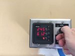
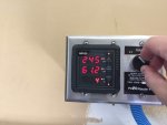
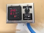
I had a hard time finding a single meter that would measure current in amps on both legs, voltage, *and* frequency. I found one by NoOutage.com called the PowerMeter 6 (NGV25-SW). It can also show the Power Factor, Total Operating Time on generator, and the load in kW.

It's basically a 3 gang box, meter with LED display, display switch for L1/L2/Total, and a pair of CTs. You can buy a second set of CTs for the utility power but I didn't want/need the extra expense. I paid $220 for the unit with a single pair of the smaller split CTs (24 kVA rated). It was more than I wanted to spend but it's exactly what I wanted and it I was able to support a small business here in the US.

It requires 240V power and the instructions call for using the generator feed. I used some taps and put them on the feeder cables before the breaker so I can check the frequency and voltage before switching the load to the generator.

Here are some pics. I forgot to take a picture of the 2nd display mode with kW, hours, and PF.
2018-06-09 13.20.38.jpg2018-06-09 13.20.57.jpg2018-06-09 13.21.08.jpg
 

gatorbob

Member
120
21
18
Location
Saint Augustine, FL
Those pictures are of it mounted on my garage wall next to my transfer switch. I zoomed in so the display would show up better. I'd like to recess mount it but that's a project for when it gets cool again.

The plan is to have the ability to check on things without going outside. My house's breaker box is a 3 feet away so I can do some load management and see the load in real time.
 

gatorbob

Member
120
21
18
Location
Saint Augustine, FL
That might be something it can't do. I need to see what happens when I press the up and down buttons with it running. I can also email the guy.

I am not that electrically literate so here's a 101 kind of question. Isn't the voltage always going to be the same on each leg from the generator? It's single phase - split, right? Although, I agree it would be nice for that switch to show the actual line voltage.
 

csheath

Active member
714
213
43
Location
FL
No. It can vary depending on load or resistance. My unit had a problem with voltage dropping on L1 under load. Both lines remain steady now that it's fixed.
 

csheath

Active member
714
213
43
Location
FL
If you devloped or had a problem like I did it would show up as an overall voltage drop. It wasn't until I checked the individual lines that I found mine was only dropping on L1.
 

Chainbreaker

Well-known member
1,796
1,992
113
Location
Oregon
...It's basically a 3 gang box, meter with LED display, display switch for L1/L2/Total, and a pair of CTs. You can buy a second set of CTs for the utility power but I didn't want/need the extra expense.
It requires 240V power and the instructions call for using the generator feed. I used some taps and put them on the feeder cables before the breaker so I can check the frequency and voltage before switching the load to the generator.
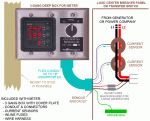
Nice setup! They do show a configuration using only 2 CTs that suggests that you can monitor either Utility or Generator power if your using an interlock type generator hookup. I do wonder if power comes back on AND you are still running generator what it would be reading...highest current values?

http://nooutage.com/images/NGV25-SW-conn4.gif
 
Last edited:

gatorbob

Member
120
21
18
Location
Saint Augustine, FL
Looking at the instructions I don't get the sense that this unit can receive data from both pairs of CTs at the same time. The drawing is different than the website. It looks like the 2nd pair of CTs are spliced into the same cables used by the first pair of CTs.

I agree that they likely assume the mechanical interlock prevents you from having both power sources active.

I've setup like you describe. I wanted to verify the power from the generator before turning any breakers on. My transfer switch has a breaker for the generator feeder itself and I put the CTs before that breaker. I keep the breaker off normally.
 

Chainbreaker

Well-known member
1,796
1,992
113
Location
Oregon
Looking at the instructions I don't get the sense that this unit can receive data from both pairs of CTs at the same time. The drawing is different than the website. It looks like the 2nd pair of CTs are spliced into the same cables used by the first pair of CTs.

I agree that they likely assume the mechanical interlock prevents you from having both power sources active.

I've setup like you describe. I wanted to verify the power from the generator before turning any breakers on. My transfer switch has a breaker for the generator feeder itself and I put the CTs before that breaker. I keep the breaker off normally.

Just to clarify, the dwg (labeled on their website as "connections generator & utility single set CTs") I linked above only shows only one one pair of CT's across L1-L2 encircling both the input side of utility service disconnect and input side of generator breaker. If I am reading their schematic correctly... in that configuration they are measuring either Utility or Generator voltage/amp (depending which power source is active). Since they have the CT's placed on the input sides of the Service disconnect and Generator breaker it would seem that there might be a situation where both could be active (with only one actually powering the breaker box due to interlock). Typical scenario with an Interlock type setup: Utility power is out and a person is running on generator power, utility power is subsequently restored (generator is still running and powering house) and has not been shutdown yet. So in that scenario, in that particular configuration shown, the CT's would be exposed to both active input lines. Just wondering what effect that might have on gauge readout...
 
Last edited:

gatorbob

Member
120
21
18
Location
Saint Augustine, FL
Ah, I looked at it wrong. Yeah, that's an interesting scenario they have in that drawing. I don't think I can get my other wires close enough to try it out... although now that I think of it, my cheaper CTs are too small anyway.

If it would behave in a way that was obvious, it would be an easy way to tell if utility power is back.
 

m32825

Active member
224
170
43
Location
Central Florida
So in that scenario, in that particular configuration shown, the CT's would be exposed to both active input lines. Just wondering what effect that might have on gauge readout...
Interesting question... If there's no load on the supply lines yet, there would be no current flowing through them, right? If you stick multiple lines with loads through a CT you get a summing of the current. Put your current clamp around L1and L3 leads with a 240 volt load and you get zero, because the currents are the same magnitude and 180 degrees out of phase. Since the current from the unconnected supply side is zero, my guess is you get an unchanged result when the power comes back on.

-- Carl
 

155mm

Chief and Indian
Steel Soldiers Supporter
1,178
389
83
Location
Guymon, OK
Last edited:

Chainbreaker

Well-known member
1,796
1,992
113
Location
Oregon
….I don't think I can get my other wires close enough to try it out... although now that I think of it, my cheaper CTs are too small anyway.
Yeah, I reviewed the pictures I took of my breaker box when I had my panel off and while my utility and genset wires are within about 6" of one another I don't think I have enough slack I could pull to get them to overlap close enough to put a CT around those pairs of wires. Since utility power is so stable not much value in monitoring Utility pwr anyway...although the meters would look kinda neat powered up 24/7.

If it would behave in a way that was obvious, it would be an easy way to tell if utility power is back.
I use the Powerback alarm module (its also listed on their website, as well as places like Home Depot) to alert me when Utility power is back on. I would rather have a loud alarm going off versus having to keep checking by going out to panel to read a meter to determine when utility power has come back on (if it would even be detectable due to no load coming off utility feed lines).
 

155mm

Chief and Indian
Steel Soldiers Supporter
1,178
389
83
Location
Guymon, OK
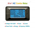
Nice, that was what I was looking for even if I had to use two of them. I spent a long time searching Amazon and never found it. Glad you did.
yeah, i ordered mine then like 2 weeks later I get an amazon popup that says, 'you might be interested in this' and it was the same one that I ordered.

I think they watch alabibi to what we order, then list that stuff on amazon
 

csheath

Active member
714
213
43
Location
FL
I use the Powerback alarm module (its also listed on their website, as well as places like Home Depot) to alert me when Utility power is back on. I would rather have a loud alarm going off versus having to keep checking by going out to panel to read a meter to determine when utility power has come back on (if it would even be detectable due to no load coming off utility feed lines).
Our panel and power back alarm is in the garage. We keep a pair of hearing protectors in the utility room. I highly suggest putting on a pair before approaching the power back alarm to turn it off.

None of my gauges worked and the one I got working was way off in accuracy. Going digital was a no brainer over restoring all those inferior gauges that came on it. Here is the cheap setup I put on my generator. I hadn't considered an inside panel but that might be neat.

IMG_1421.JPG
 

155mm

Chief and Indian
Steel Soldiers Supporter
1,178
389
83
Location
Guymon, OK
Used the gauge on a load test for a little 831a, worked very well. Also installed 2 of these on my RV 7.5KW since my wife spent 1900 smackers on an inverter that was smoked because the genny was shut down with a load still applied *not me for once*

IMG_2525[1].jpg

IMG_2523[1].jpg ps an 831a will turn 26amps for atleast 10 minutes
 
Last edited:
Top
AdBlock Detected

We get it, advertisements are annoying!

Sure, ad-blocking software does a great job at blocking ads, but it also blocks useful features of our website like our supporting vendors. Their ads help keep Steel Soldiers going. Please consider disabling your ad blockers for the site. Thanks!

I've Disabled AdBlock
No Thanks